Axial lengthening thrombus capture system

a thrombus and axial length technology, applied in the field of axial lengthening thrombus capture system, can solve the problems of significant morbidity and mortality risks, long time duration requirements, and increased healthcare costs, and achieve the effect of shortening the thrombus capture device and promoting the removal of the thrombus

Active Publication Date: 2017-08-29
VASCULAR MEDCURE INC
View PDF118 Cites 39 Cited by
  • Summary
  • Abstract
  • Description
  • Claims
  • Application Information

AI Technical Summary

Benefits of technology

[0017]In some embodiments, a method of performing a thrombectomy can include, for example, accessing the interior of a blood vessel; advancing an expanding guiding catheter through the blood vessel; positioning the expanding guiding catheter such that a distal end of the device is proximal to a thrombus; retracting the expanding guide catheter outer member to expand a funnel tip and exposing an expandable inner member; advancing a thrombus capture device comprising a capture assembly through the expanding guide catheter; positioning the thrombus capture device such that a distal end of the device is distal to or within the thrombus; and actuating the capture assembly to isolate the thrombus within the capture device. The capture assembly can be movable from a first configuration having a first axial length and a second configuration having a second axial length, the second axial length being different from the first axial length. The width of the capture assembly may not substantially change from the first configuration to the second configuration. The method can also include retracting the capture assembly with the thrombus into an expanding guide catheter funnel tip and expandable inner body. The method can also include axially lengthening the thrombus capture device distally and retracting the thrombus into the funnel tip of the expanding guide catheter. The method can further include radially shortening the thrombus capture device to compress the thrombus and promote removal of the thrombus.

Problems solved by technology

While thrombolytic agents can be effective in dissolving blood clots, they require a long time duration in order for the agents to dissolve the blood clots; thus patients may need to remain in the hospital intensive care unit (ICU) during thrombolytic infusion.
Relatively long lengths of stay can increase healthcare costs significantly.
A major limitation for these thrombolytic agents is that they can potentially cause intracranial, gastrointestinal, retroperitoneal, and pericardial bleeding, among other sites, which can be often life-threatening and cause significant morbidity and mortality risks.
However, current mechanical therapies have some major limitations.
The debris removed from mechanical treatment can travel distally creating additional embolization.
The small size devices are unable to remove large amount of blood clots in short time periods thus patients may become hemodynamically instable.
Catheter-based removal of blood clots from larger blood vessels (e.g., pulmonary arteries) have had limited success compared to smaller blood vessels (e.g., coronary arteries).
Fragmentation thrombectomy breaks blood clots into smaller pieces, most of which travel further downstream, resulting in distal embolization.
This method poses risk of hemolysis.
This procedure is therefore time-consuming and inefficient.
Once the blood clots are broken into small pieces, the debris can migrate distally and create unwanted emboli.
Rheolytic therapy poses the risk of hemolysis.
Additionally, the ability to suction is limited due the small catheter size suctioning large emboli.
These limitations cause unnecessary duress to the user and risk to the patient.
Catheter-based removal of blood clots in general also has a major limitation when distal working space within a body lumen is limited.
Conventional devices may require full axial and / or radial deployment and expansion to be functional, and as such flexibility to use such devices for a variety of clinical situations involving differing clot or other material sizes to be removed can be very limited.
Therefore, conditions where there is limited distal space of blood vessels can render these conventional devices ineffective.
It is evident that all of the therapeutic options available to patients with blood clots or other undesirable material in blood vessels and other body lumens have limitations.
Anticoagulation only limits propagation of clots but does not actively remove it.
Thrombolytic therapy poses a risk of major bleeding.
Catheter embolectomy is not effective to manage removal of material in large vessels.
Additionally, these devices require distal space to fully deploy to be functional thus ineffective in tight distal spaces.
Surgical embolectomy can be highly effective but highly invasive, and has a high rate of morbidity and mortality.

Method used


Image

  • Axial lengthening thrombus capture system
  • Axial lengthening thrombus capture system
  • Axial lengthening thrombus capture system

Examples


Embodiment Construction

[0107]The present invention provides, in some embodiments, systems and methods that can be delivered percutaneously in a body to retrieve and removal materials including blood clots, stones / calculi, and / or foreign materials in a body lumen, including a blood vessel, such as an arterial vessel or a venous vessel within the circulatory system. The present invention can, in some embodiments, also apply to nonvascular areas to treat, for example, gallstones, kidney stones, common bile duct stones, and the like.

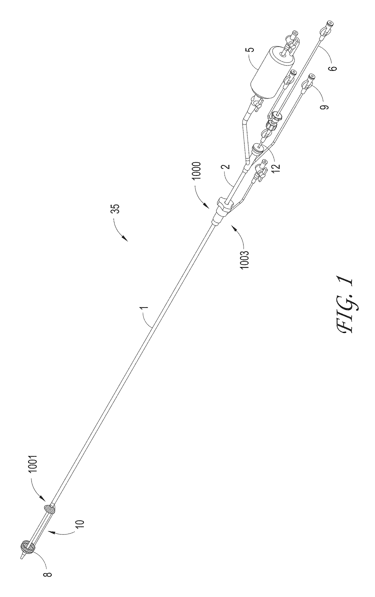
[0108]Systems can be delivered percutaneously, via a cut-down approach, a thoracoscopic approach, or via other approaches, for example, using a catheter system 35, of which a perspective view of an embodiment is shown in FIG. 1. FIG. 1 also illustrates examples of various possible elements that can be included in a material capture system, according to some embodiments of the invention. As illustrated in FIG. 1, included in some embodiments are any number of, such as one, two, or ...


PUM


Abstract

Systems and methods can remove material of interest, including blood clots, from a body region, including but not limited to the circulatory system for the treatment of pulmonary embolism (PE), deep vein thrombosis (DVT), cerebrovascular embolism, and other vascular occlusions.

Description

PRIORITY CLAIM[0001]This application claims the benefit under 35 U.S.C. §120 as a continuation-in-part application of U.S. patent application Ser. No. 15 / 230,109 filed on Aug. 5, 2016, which claims the benefit under 35 U.S.C. §119(e) as a nonprovisional application of each of U.S. Provisional App. Nos. 62 / 202,074 filed on Aug. 6, 2015, 62 / 273,418 filed on Dec. 30, 2015, and 62 / 345,863 filed on Jun. 6, 2016. Each of the aforementioned priority applications is hereby incorporated by reference in their entireties.BACKGROUND[0002]Field of the Invention[0003]The invention relates to, in some aspects, systems and methods to remove materials of interest, including blood clots, from a body region, including but not limited to the circulatory system for the treatment of pulmonary embolism (PE), deep vein thrombosis (DVT), cerebrovascular embolism, and other vascular occlusions.[0004]Description of the Related Art[0005]It is understood that undesirable materials such as blood clots (which cou...

Claims


Application Information

Patent Timeline
Patent Type & Authority Patents(United States)
IPC IPC(8): A61B17/221A61F2/01A61B17/3207A61M29/00A61B17/22A61B17/00A61B17/32
CPCA61F2/013A61B17/221A61B17/320758A61B2017/00867A61B2017/00871A61B2017/00938A61B2017/00942A61B2017/2212A61B2017/2217A61B2017/22038A61B2017/22079A61B2017/22081A61B2017/22084A61B2017/320052A61B2017/320716A61B2017/320775A61F2002/011A61F2002/016A61B17/32075A61B2017/22034A61B2217/005A61F2/011A61M1/79
Inventor NGUYEN, THANH VANNGUYEN, DUYNGO, TUNG HOANG
Owner VASCULAR MEDCURE INC
Why Eureka
Try Eureka