Inductive energy supply unit

a technology of inductive energy supply and inductive current supply, which is applied in the direction of data switching details, data switching current supply, instruments, etc., can solve the problems of potential separation between primary and secondary sides, and the relative free positioning of primary and secondary sides is not possible, and achieves high insulation class, large capture cross-section of flux lines, and cost-effective

Inactive Publication Date: 2017-09-19
PHOENIX CONTACT GMBH & CO KG
View PDF41 Cites 1 Cited by
  • Summary
  • Abstract
  • Description
  • Claims
  • Application Information

AI Technical Summary

Benefits of technology

[0012]If the first electronics has signal input connectors and the second electronics has signal output connectors it is advantageous to accommodate the first and second electronics on a common circuit board and to connect the first electronics to the second electronics via a data signal coupling line. In this embodiment, the signal connectors are arranged on opposite side of the electronics, that is, at the greatest insulation distances possible.
[0014]As is well known, a coil having helical turns produces magnetic flux lines which, inside the coil, extend parallel to the coil axis and bend outwards outside of the coil and turn round and run parallel or almost parallel to the coil axis in order to bend inward again towards the inside of the coil. Axially parallel flux lines stand perpendicular or almost perpendicular on planes spanned by the receiving coils so that effective coupling between transmitting coils and receiving coils takes place. If the receiving coils are accommodated on a circuit board, it is advantageous to let the turns extend spirally. Such coils can be produced in a cost-effective manner and have a large capture cross-section for flux lines.
[0015]Industrial installations often need numerous electronic modules which are often fixed along a holding device within control cabinets. For such an application, the invention provides to arrange a number of transmitting coils along the holding device, and a plurality of electronic modules equipped with at least two receiving coils can be positioned relatively free in a row along the holding device and can be secured thereon. In this manner it is possible, to supply electrical energy to a plurality of electronic modules, each of which can have different dimensions, wherein insulation is provided to a large extent by galvanically separating power supply and signal processing or data processing, and in addition, signal or data processing can achieve a high insulation class.

Problems solved by technology

Because of the ferromagnetic limbs, relatively free positioning between primary and secondary sides is not possible.
This results in potential separation between an electrical energy supply unit and an energy consumer unit, but not in a separation between three potential groups.

Method used


Image

  • Inductive energy supply unit
  • Inductive energy supply unit
  • Inductive energy supply unit

Examples


Embodiment Construction

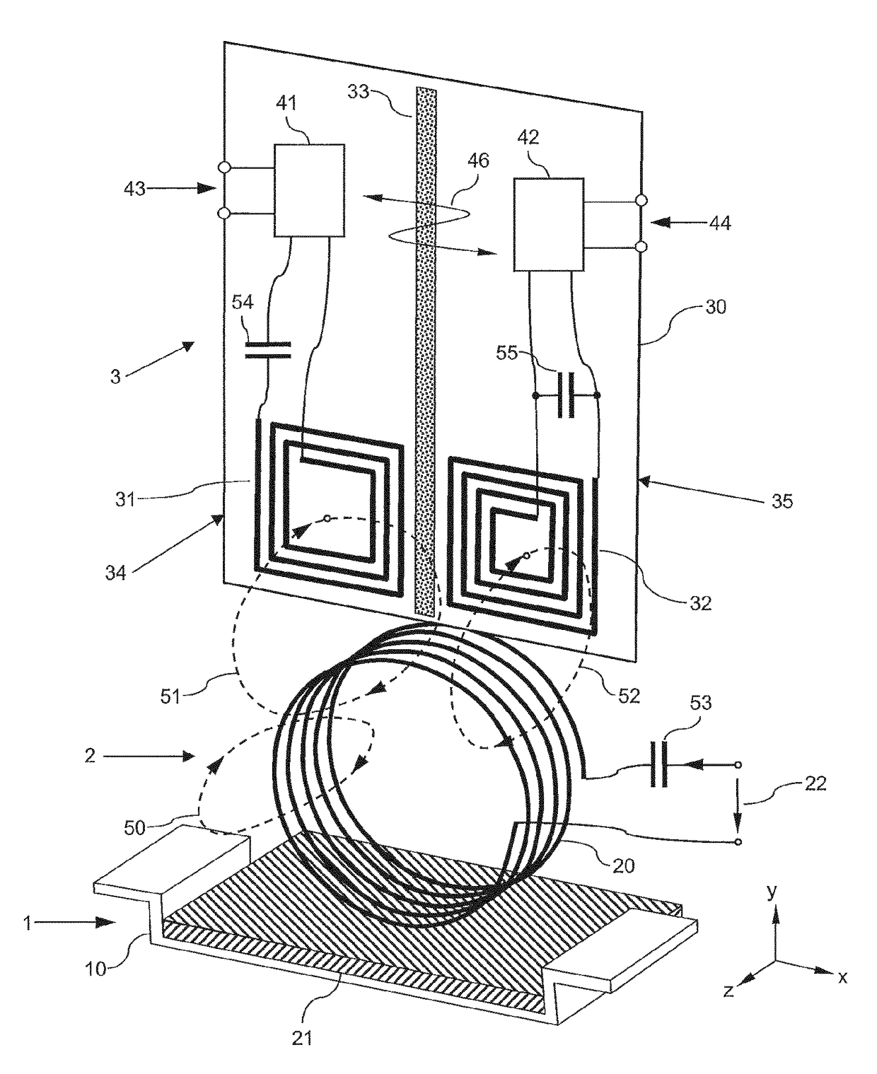
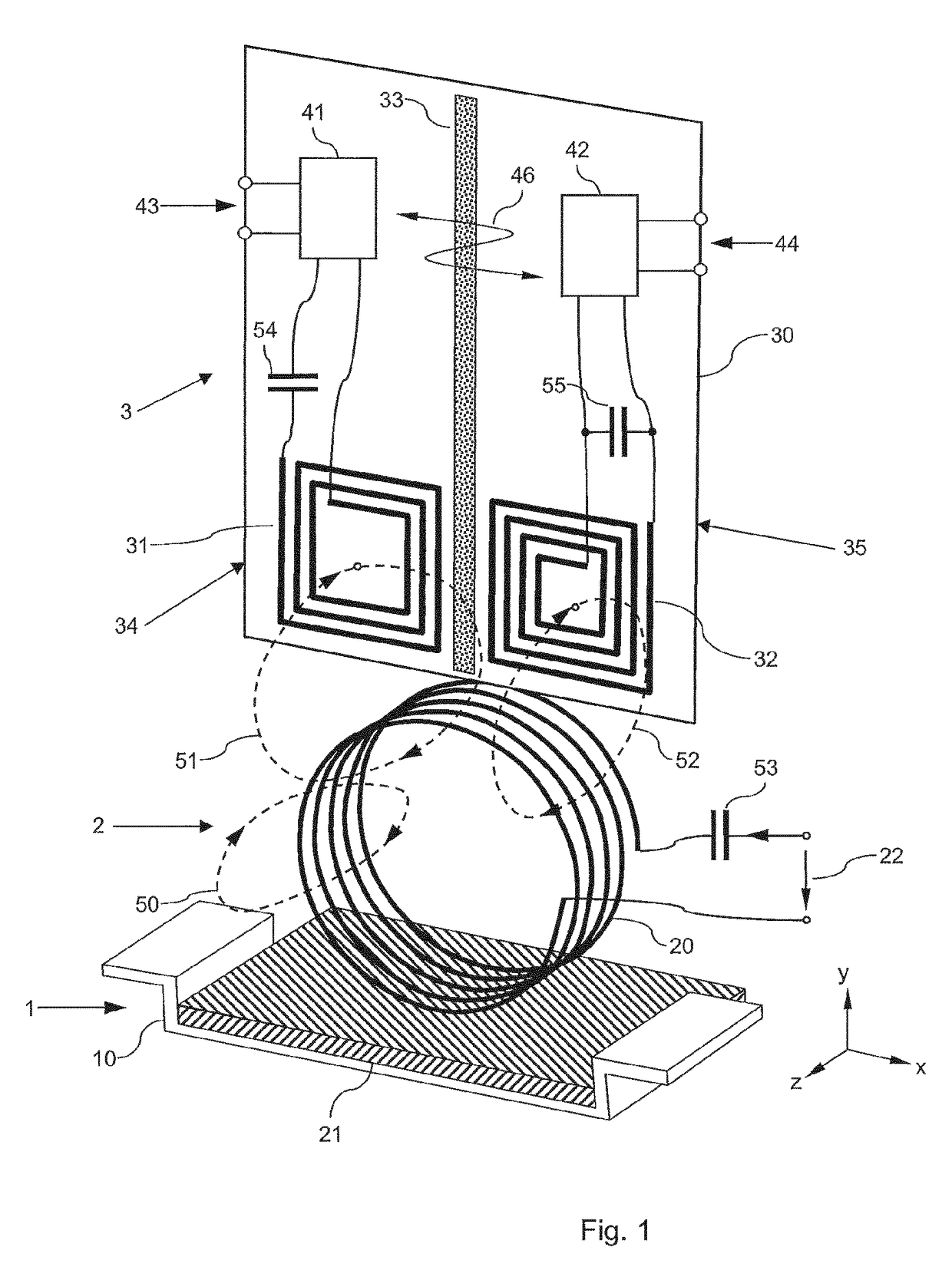
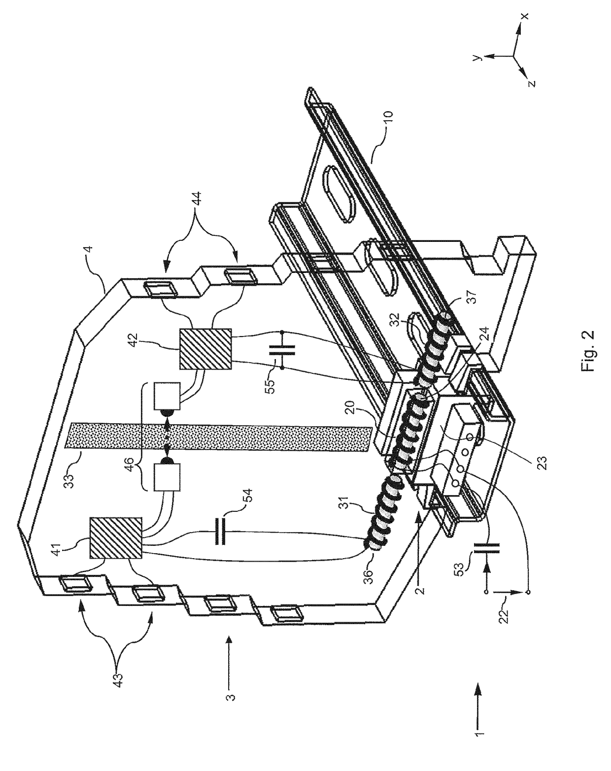
[0019]On a support rail 10 of an elongated module holding device 1, a transmitting coil 20 is secured which is supplied via an alternating input voltage 22 and thus acts as energy supply part 2. At a certain distance from the transmitting coil 20, a circuit board 30 is held by means of a housing 4 (FIG. 2) which is supported on the rail 10. Two spiral-shaped flat receiving coils 31, 32 which are separated from one another by an insulating area of separation 33 are fitted as conductor paths on the circuit board 30. The first receiving coil 31 is connected to a first electronics 41 and the second receiving coil 32 is connected to a second electronics 42. The components 31, 41, 54 form a first energy receiving part 34, and the components 32, 42, 55 form a second energy receiving part 35 of an electronic module 3.

[0020]The first electronics 41 can represent a signal or data input electronics and the second electronics 42 can be a signal or data output electronics of the electronic modul...


PUM

PropertyMeasurementUnit
electrical energyaaaaaaaaaa
magnetic fieldaaaaaaaaaa
energyaaaaaaaaaa

Abstract

A device for supplying electrical energy and / or supplying data to an electronic module, comprising a transmitting coil that has a coil axis and at least two energy receiving parts that are arranged side by side and have receiving coils, the coil axes of which run in the same direction or run parallel to the transmitting coil axis. Each of the coils is integrated in resonance circuits. The energy receiving parts supply electronics and, together with the same, are galvanically separated from one another by an insulating area of separation which is bridged by a data signal coupling line.

Description

FIELD OF THE INVENTION[0001]The invention relates to a device for supplying electrical energy and / or supplying data to one or a plurality of electronic modules.BACKGROUND OF THE INVENTION[0002]For galvanically separated power supply, transformers or energy transmitters having a primary coil and a secondary coil which form an isolating distance are frequently used. In EP 1 885 085 A1 there are, separated from one another, an energy transmission interface and a data transmission interface for contactless connection of a bus subscriber. Two secondary windings and two processing units per bus subscriber are not provided.[0003]Also, interfaces are known via which, in addition to energy, signals or data can also be transmitted bidirectionally. In WO 98 / 15069 A1, a ferromagnetic core limb provided with a primary coil for energy transmission and with a primary coil for data transmission in interaction with a ferromagnetic core limb provided with a secondary coil for energy input and a secon...

Claims


Application Information

Patent Timeline
Patent Type & Authority Patents(United States)
IPC IPC(8): H01F27/42H04L12/10H04B5/00H01F37/00G02B6/00H02J7/02H01F38/14
CPCH04B5/0037G02B6/00H01F38/14H02J7/025H04B5/005H04B5/0031H04B5/0093H04L12/10H02J50/05H02J50/10H02J50/12
Inventor SCHOLZ, PETER-DOMINIK
Owner PHOENIX CONTACT GMBH & CO KG
Why Eureka
Try Eureka