
Stent for neutron capture therapy and method of manufacture therefor

a neutron capture and neutron technology, applied in the field of intravascular neutron capture therapy, can solve the problems of clogging the vessel, inaccurate dose distribution, and several problems common to all devices for this type of intravascular, and achieve the effect of large capture cross-section and easy repeatability

Inactive Publication Date: 2006-08-10
ABBOTT LAB VASCULAR ENTERPRISE
View PDF18 Cites 2 Cited by
  • Summary
  • Abstract
  • Description
  • Claims
  • Application Information

AI Technical Summary

Benefits of technology

"The present invention provides methods and apparatus for neutron capture therapy that can be used during a stenting procedure. The stent has a stable target nuclide that can capture thermal neutrons and produce ionization radiation around the stent. The dose rate can be controlled by adjusting the concentration of target nuclide and thermal neutron flux. The therapy can be repeated as needed. The stent can be easily made using existing methods. The technical effects of the invention include temporal separation between balloon dilation and radiation delivery, ensuring only patients who need therapy are treated, and allowing for repeat therapy as needed."

Problems solved by technology

One drawback associated with previously known stents is the restenosis effect, i.e., the epithelial cells of the vessel walls adjacent to the ends of the stent and surrounding the stent may experience excess growth of cells, thereby clogging the vessel.
Several problems are common to all devices for this type of intravascular brachytherapy.
Dimensions are small, and misplacement of the radiation source by as little as a few millimeters can give rise to a very inaccurate dose distribution.
Furthermore, working with radioactive sources in a catheterization laboratory is problematic, as a new catheterization has to be performed, thereby adding risk to the patient and costs to the treatment.

Method used


Image

  • Stent for neutron capture therapy and method of manufacture therefor
  • Stent for neutron capture therapy and method of manufacture therefor
  • Stent for neutron capture therapy and method of manufacture therefor

Examples


Embodiment Construction

[0023] The present invention provides a stent comprising a stable nuclide element that may be externally activated by thermal neutrons, thereby providing localized neutron capture therapy in the vicinity of the vessel around the stent. Since radiation is applied by an external source, therapy may be delivered at any time after placement of the stent and easily may be repeated. Furthermore, unlike other known radiation techniques, the present invention ensures that neutron capture therapy is only provided to patients where radiation exposure is expected to provide therapeutic benefit.

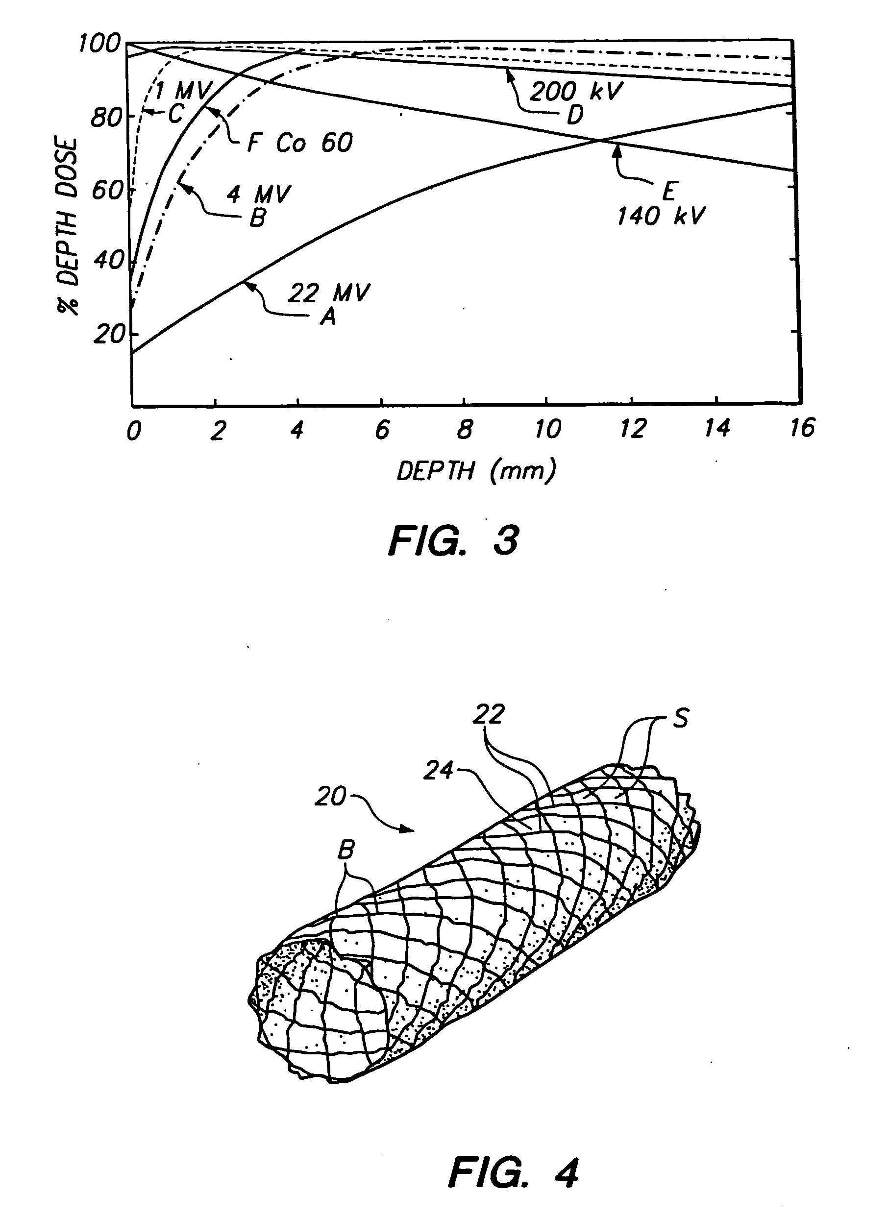
[0024] In accordance with the principles of the present invention, a stent is constructed including a material having a high neutron capture cross-section, for example, greater than 103 barns, and that provides a high quality of radiation emission. As will of course be apparent, the irradiation dose provided by the stent after irradiation by an external source also depends upon the amount of stable nucl...


PUM


Abstract

Improved method and apparatus for neutron capture therapy are disclosed, which may beneficially be used to counteract restenosis. An improved stent and a method for manufacturing the stent are also presented. The stent comprises a stable nuclide having a large neutron capture cross-section. When a clinical need exists for radiation therapy, the stent is irradiated with thermal neutrons, thereby giving rise to radiation in the proximity of the stent to a therapeutic benefit. Since radiation is applied by an external source, it can be delivered at any time after placement of the stent and easily can be repeated. The stent only contains stable nuclides and therefore can be handled without the precautions needed when handling radioactive matter.

Description

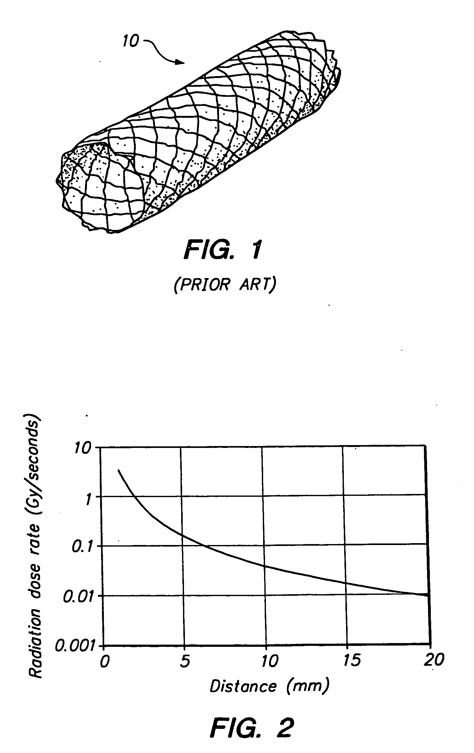
FIELD OF THE INVENTION [0001] The present invention relates to intravascular neutron capture therapy. More particularly, the present invention provides methods and apparatus for making and using an implantable stent comprising a material capable of reducing restenosis, thereby improving long-term patency of the implanted stent. BACKGROUND OF THE INVENTION [0002] Over the past 20 years, the number of percutaneous coronary revascularization procedures has increased to more than one million per year. About 50% of these procedures include stent implantation. A stent is often designed as a thin metal wire mesh, which keeps a fabric in a desired shape, for instance forming a very thin tube providing an open channel for a fluid. FIG. 1 illustrates an example of such a stent, which is commercially available from JOMED AB, Helsingborg, Sweden. A polyfluorotetraethylene (“PFTE”) graft material integrated into the stent is used to seal off a perforated or ruptured artery wall. [0003] One drawb...

Claims


Application Information

Patent Timeline
Patent Type & Authority Applications(United States)
IPC IPC(8): A61F2/06A61F2/00A61F2/82A61K41/00A61N5/10G21G4/08
CPCA61F2/82A61F2210/0095G21G4/08A61N5/1002A61K41/009
Inventor LUNDQVIST, HANS
Owner ABBOTT LAB VASCULAR ENTERPRISE
Learn More