Method for modifying a solar thermal power plant operating on conventional oil based technology into a hybrid solar thermal power plant and such a hybrid solar thermal power plant

a solar thermal power plant and hybrid technology, applied in the direction of solar heat generation, steam generation using hot heat carriers, lighting and heating apparatus, etc., can solve the problems of low efficiency of known low efficiency of steam transfer cycle into electricity, and inability to meet the needs etc., to achieve the effect of reducing the cost of operation and maintenance, and improving the efficiency of solar thermal power plants

Active Publication Date: 2017-09-26
STAMICARBON ACTING UNDER THE NAME OF MT INNOVATION CENT +2
View PDF10 Cites 0 Cited by
  • Summary
  • Abstract
  • Description
  • Claims
  • Application Information

AI Technical Summary

Benefits of technology

[0007]A further advantage of such a hybrid system lies in the fact that the operation time of the hybrid thermal solar power plant is increased compared to the operation time of the conventional oil based solar thermal power plant. Besides, the hybrid system is a safer system than the conventional oil based solar thermal power plant due to the fact that usage and storage of molten salts is less hazardous than usage and storage of hot oil. Furthermore, in the hybrid system of the invention, the molten salt handling system is less complicated than the oil handling system or a solar power plant based exclusively on molten salt as heat transfer medium since it only exchanges heat with medium temperature steam which is above the melting temperature of the molten salt. The hybrid system further enables using the existing equipment of the oil based solar thermal power plant and the molten salts based solar thermal power plant to the fullest.
[0008]Preferably, in the hybrid solar thermal power plant, the oil based solar thermal power plant is configured for providing saturated steam to the solar thermal power plant. In the oil based solar thermal power plant, the saturated steam will be heated to a temperature of 300-345° C., preferably to a temperature of 310-320° C., for example 315° C. These temperatures correspond to a pressure of about 85 bar for saturated steam of 300° C. to a pressure of about 150 bar for saturated steam of 345° C. To produce the saturated steam at said temperatures, the hot oil temperatures in the oil based solar thermal power plant will be in the range of 340-380° C., preferably between 340-360° C., more preferably between 345-350° C. Consequently, due to the relatively low temperatures of the hot oil, the bulk temperature and the film temperature of the hot oil in the heat exchanger of the oil based solar thermal power plant will be relatively low as well, at least lower than the bulk temperature and the film temperature in conventional oil based solar thermal power plants or in hybrid solar thermal power plants in which the oil based thermal power plant is configured to superheat the steam. Thus, in the hybrid solar thermal power plant according to the invention, degradation of the hot oil will be minimized or at least significantly reduced, thereby extending the lifetime of the oil and preventing issues like coke formation in the heat exchanger of the oil based thermal power plant which may lead to fouling and a reduced heat transfer coefficient of said heat exchanger.
[0009]Preferably, in the hybrid solar thermal power plant, the solar thermal power plant is configured for subsequently superheating the steam to at least 450° C., preferably to at least 500° C., for example between 500° C. and 1000° C. For instance, when using Na / K nitrates as molten salts mixture, the steam may be heated to a temperature of approximately 500° C. By heating / reheating the steam to said temperatures and subsequently supplying it to the turbine, the efficiency of the turbine is maximized.
[0016]Additionally to providing the reheating section of the turbine in fluid connection with the solar collection system of the molten salts based solar thermal power plant, the reheating section may, according to a further aspect of the invention, be provided in fluid connection with an additional solar collection system configured for heating a molten salts mixture to reheat the steam coming directly from the oil based thermal power plant or coming from the first turbine section before supplying it to the second turbine section to generate electricity and / or for heating the molten salts mixture, for instance in an additional storage facility, to heat the steam generated from the supplied boiler feed water. Generating steam by means of vaporization of the supplied boiler feed water and subsequently heating the steam for instance to approximately 520-540° C. provides the advantage that the turbine is able to generate electricity even when there is no solar radiation available to heat the molten salts mixture by means of the solar collection system.
[0021]According to another aspect of the invention, the plant may comprise a back-up boiler system to heat the molten salts mixture and / or to preheat the boiler feed water, for instance to maximize operation time of the hybrid solar thermal power plant in case of absence of solar radiation.

Problems solved by technology

However, the oil based thermal fluid may dissociate or otherwise break down or become less effective at transferring heat if said heat transfer media operate at very high temperatures.
Due to this restricting behaviour, conventional plants generating solar thermal energy are typically limited to operate at about 400° C. At such temperature the overall efficiency of the cycle to transfer steam into electricity may be limited to less than 32%.
However, the known solar thermal power plants may still have efficiency problems.

Method used


Image

  • Method for modifying a solar thermal power plant operating on conventional oil based technology into a hybrid solar thermal power plant and such a hybrid solar thermal power plant
  • Method for modifying a solar thermal power plant operating on conventional oil based technology into a hybrid solar thermal power plant and such a hybrid solar thermal power plant
  • Method for modifying a solar thermal power plant operating on conventional oil based technology into a hybrid solar thermal power plant and such a hybrid solar thermal power plant

Examples


Embodiment Construction

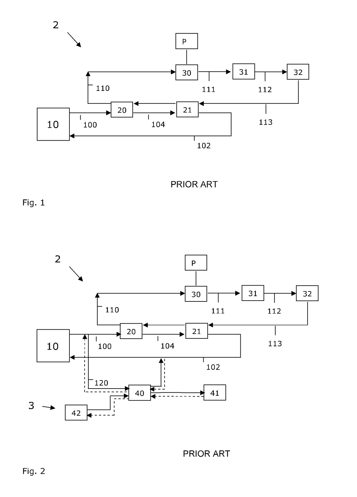
[0032]In FIG. 1, an example of a prior art solar thermal power plant 2 based on conventional oil based technology is shown. The solar thermal power plant 2 comprises a solar collection system 10. The solar collection system 10 comprises one or more radiation absorber tubes and a plurality of trough collectors, such as single axis parabolic reflectors. Alternatively, the solar collection system 10 may be provided with any suitable means for concentrating solar radiation, such as Fresnel collectors. The radiation absorber tubes contain a thermal fluid used as heat transfer fluid, such as diathermic oils which are commercially available, for instance commercially available under the trade name Terminal® VP1. Flowing inside the radiation absorber tubes, the heat transfer fluid is heated by the exposure to concentrated solar radiation. The heat transfer fluid may be heated to an upper threshold temperature that has to be chosen as the highest safe working temperature for the heat transfe...


PUM


Abstract

A method for modifying a solar thermal power plant operating on conventional oil based technology into a hybrid solar thermal power plant includes: providing an oil-based solar thermal power plant, which includes a solar collection system with at least one radiation absorber tube containing a heat transfer oil to be heated by the solar collection system; providing a molten salts solar thermal power plant, which includes a solar collection system to heat a molten salts mixture; and coupling the respective plants such that the hybrid solar thermal power plant is configured to heat medium temperature steam generated by the oil based solar power plant by the molten salts mixture thereby producing high temperature steam and subsequently supplying it to a steam turbine to generate electricity.

Description

FIELD OF THE INVENTION[0001]The present invention relates to the field of solar thermal power plants operating on conventional oil based technology.BACKGROUND[0002]Solar thermal power plants operating on conventional oil based technology are known from practice. Such known conventional oil based solar thermal power plants comprise a solar collection system having one or more tube radiation absorbers and a plurality of trough collectors, such as single axis parabolic reflectors or Fresnel collectors configured to receive and reflect incoming solar radiation onto a radiation absorber, which is formed as a tube. A thermal fluid, constituting a heat transfer medium, which is typically a liquid such as oil, flows within the radiation absorber tube. The thermal energy transported by the thermal fluid is used to generate steam which in turn is expanded into a turbine, in order to generate electricity in a conventional way, by coupling the axle of the turbine to a generator. Then, the steam...

Claims


Application Information

Patent Timeline
Patent Type & Authority Patents(United States)
IPC IPC(8): F01K13/00F22B1/00F01K3/06F01K7/16F03G6/00F01K3/08F22B1/02F01K7/22F01K3/24F01K3/00
CPCF01K13/00F01K3/004F01K3/08F01K3/24F01K7/16F01K7/22F03G6/005F22B1/006F22B1/028Y02E10/46Y02E20/16
Inventor IAQUANIELLO, GAETANOCAPOFERRI, DANIELAFABRIZI, FABRIZIOEPSTEIN, MICHAEL
Owner STAMICARBON ACTING UNDER THE NAME OF MT INNOVATION CENT
Why Eureka
Try Eureka