Photoplethysmography sensor apparatus and method

a sensor and photoplethysmography technology, applied in the field of photoplethysmography sensor apparatus, photoplethysmography sensor method, and photo, can solve the problems of inability to achieve track-and-hold topology, less suited to ambient light of ‘ac kind’, etc., and achieve the effect of saving battery power and saving costs and/or spa

Active Publication Date: 2017-10-03
KONINKLJIJKE PHILIPS NV
View PDF18 Cites 3 Cited by
  • Summary
  • Abstract
  • Description
  • Claims
  • Application Information

AI Technical Summary

Benefits of technology

[0020]In a further preferred embodiment, said photoplethysmography sensor apparatus comprises an analog-to-digital converter configured to receive the output signal from said synchronous detector. Employing an analog-to-digital converter in combination with said synchronous detector is preferable for the following reasons. A synchronous detector may be implemented in the analog or in the digital domain. Using it in the analog domain has the advantage that after the synchronous detection (which preferably includes the low pass filter) the bandwidth is limited to what is needed (for instance, approximately 15 Hz) and that all asynchronous interference has been removed. This means that a low speed high resolution ADC can be used. If SD is done in the digital domain then the bandwidth requirements are higher (depending on the LED pulse frequency) and thus AD conversion will be more expensive and / or less accurate. Furthermore, asynchronous interference is still present and needs to be considered in ADC selection. The advantage of implementing a synchronous detector in the digital domain involves an increased flexibility (because it is software and / or programmable) and, because less external components are needed. Further advantages of implementing a synchronous detector in the digital domain relate to smaller size and potentially lower power consumption.
[0027]In a further preferred embodiment, said photoplethysmography sensor apparatus further comprises a sample-and-hold circuit configured to store a signal output by said transimpedance amplifier. Preferably, the light source unit (such as, e.g., an LED) is driven with a low duty cycle to save battery power. This means that there is only a short period available for sampling the actual photoplethysmography signal. A sample-and-hold circuit will extend this time. However, many modern ADCs (typically referred to as sampling ADCs) already include a sample-and-hold component. Therefore, including a sample and hold circuit will provide an advantage, e.g., in case it is desired to avoid using an ADC in order to save costs and / or space by using the hardware already present in a microcontroller. There are several known possibilities to build a (low speed) ADC using a microcontroller. One possibility refers to building an SAR-ADC by using a microcontroller's analog output in combination with its voltage comparator.

Problems solved by technology

However, the integration part implies a low-pass filter action, and therefore is less suited for ‘AC kind’ of ambient light.
This cannot be achieved with a track-and-hold topology, because there the error can only become zero at infinite amplification.

Method used


Image

  • Photoplethysmography sensor apparatus and method
  • Photoplethysmography sensor apparatus and method
  • Photoplethysmography sensor apparatus and method

Examples


Embodiment Construction

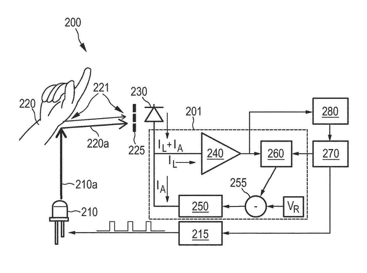
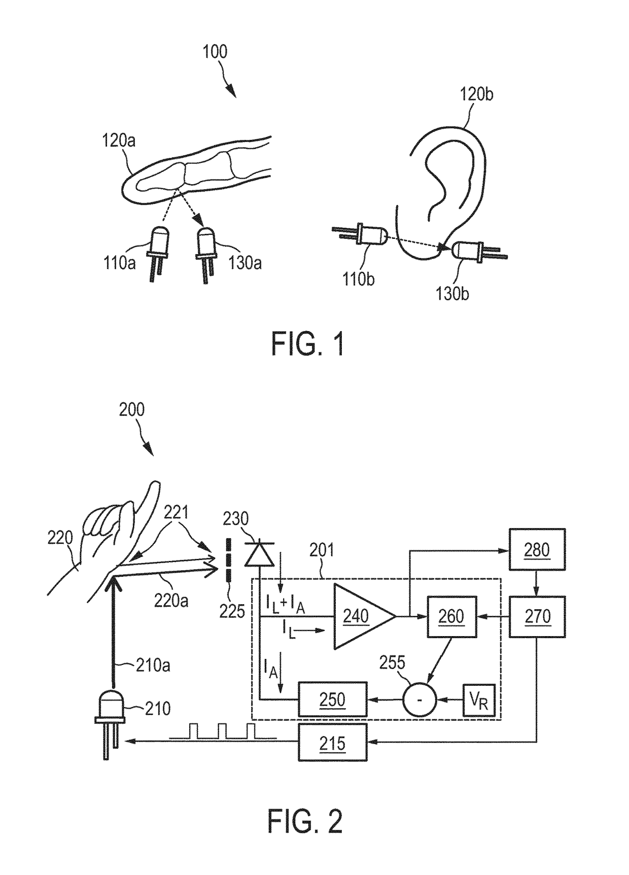
[0045]The present invention relates to a photoplethysmography sensor apparatus, a photoplethysmography sensor method, and a photoplethysmography sensor computer program. It is proposed to measure a photoplethysmographic signal without ambient light interference. Ambient light signals are rejected by subtraction of a compensation current at the input of a transimpedance amplifier. The compensation current is controlled via a closed loop, without interfering with the low duty cycle operation of a photoplethysmography LED.

[0046]FIG. 1 illustrates the basic principle of PPG. PPG refers to acquiring a volumetric organ measurement by optical means. In example 100 shown in FIG. 1, a light-emitting diode 110a outputs light towards a human finger 120a. The light is partly absorbed and partly reflected by finger 120a. Reflected light is observed by photo diode or transistor 130a. Further, in example 100, a light-emitting diode 110b outputs light towards a human earlobe 120b. The light is part...


PUM


Abstract

The present invention relates to a photoplethysmography sensor apparatus (200, 300), a photoplethysmography sensor method (400), and a photoplethysmography sensor computer program product. It is proposed to measure a photoplethysmographic signal without ambient light interference. Ambient light signals are rejected by subtraction of a compensation current at the input of a transimpedance amplifier (240, 340). The compensation current is controlled via a closed loop, without interfering with the low duty cycle operation of a photoplethysmography LED (210, 310).

Description

CROSS-REFERENCE TO PRIOR APPLICATIONS[0001]This application is the U.S. National Phase application under 35 U.S.C. §371 of International Application No. PCT / EP2015 / 063858, filed on Jun. 19, 2015, which claims the benefit of European Patent Application No. 14174974.7, filed on Jun. 30, 2014. These applications are hereby incorporated by reference herein.FIELD OF THE INVENTION[0002]The invention relates to a photoplethysmography sensor apparatus, a photoplethysmography sensor method, and a photoplethysmography sensor computer program.BACKGROUND OF THE INVENTION[0003]Photoplethysmography (PPG) refers to acquiring a volumetric organ measurement by optical means. Frequently, pulse oximeters are employed, which detect changes in light absorption properties of the human skin. Typically, a transmissive or reflective blood PPG sensor monitors the perfusion of blood to the dermis and subcutaneous tissue of the skin through absorption measurement at a specific wavelength. Besides light origina...

Claims


Application Information

Patent Timeline
Patent Type & Authority Patents(United States)
IPC IPC(8): A61B5/08A61B5/024A61B5/00
CPCA61B5/02416A61B5/02427A61B5/7203
Inventor VERMEULEN, OLAF THOMAS JOHAN ANTONIEGEENEN, KOEN
Owner KONINKLJIJKE PHILIPS NV
Why Eureka
Try Eureka