Trans-impedance amplifier with increased dynamic range

a technology of trans-impedance amplifier and dynamic range, which is applied in the direction of amplifier combinations, negative-feedback-circuit arrangement, instruments, etc., can solve problems such as discontinuities in the overall output, and achieve the effect of reducing the accuracy and dynamic range of the wide-dynamic-range amplifier

Active Publication Date: 2017-10-31
MKS INSTR INC
View PDF3 Cites 4 Cited by
  • Summary
  • Abstract
  • Description
  • Claims
  • Application Information

AI Technical Summary

Benefits of technology

[0015]As the collector current further increases and the low-gain amplifier approaches saturation mode, the current steering element may cause additional incremental collector current to be steered to a bleed-off path. The output of the high-gain linear amplifier and the low-gain linear amplifier may be sampled and combined to produce an aggregate output corresponding to the received collector current. Steering excess current to a bleed-of

Problems solved by technology

This finite “un-saturate” time may create discontinuities in the overall output a

Method used


Image

  • Trans-impedance amplifier with increased dynamic range
  • Trans-impedance amplifier with increased dynamic range
  • Trans-impedance amplifier with increased dynamic range

Examples


Embodiment Construction

[0040]A description of example embodiments of the invention follows.

[0041]The teachings of all patents, published applications and references cited herein are incorporated by reference in their entirety.

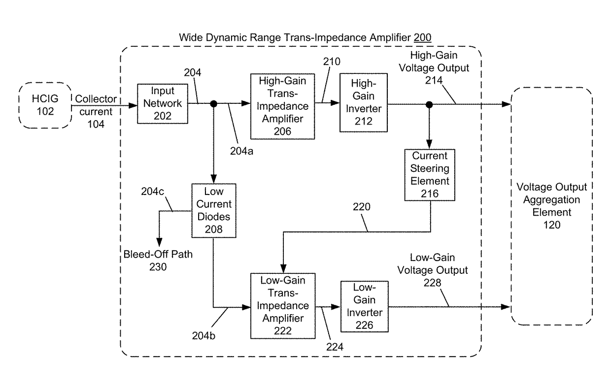
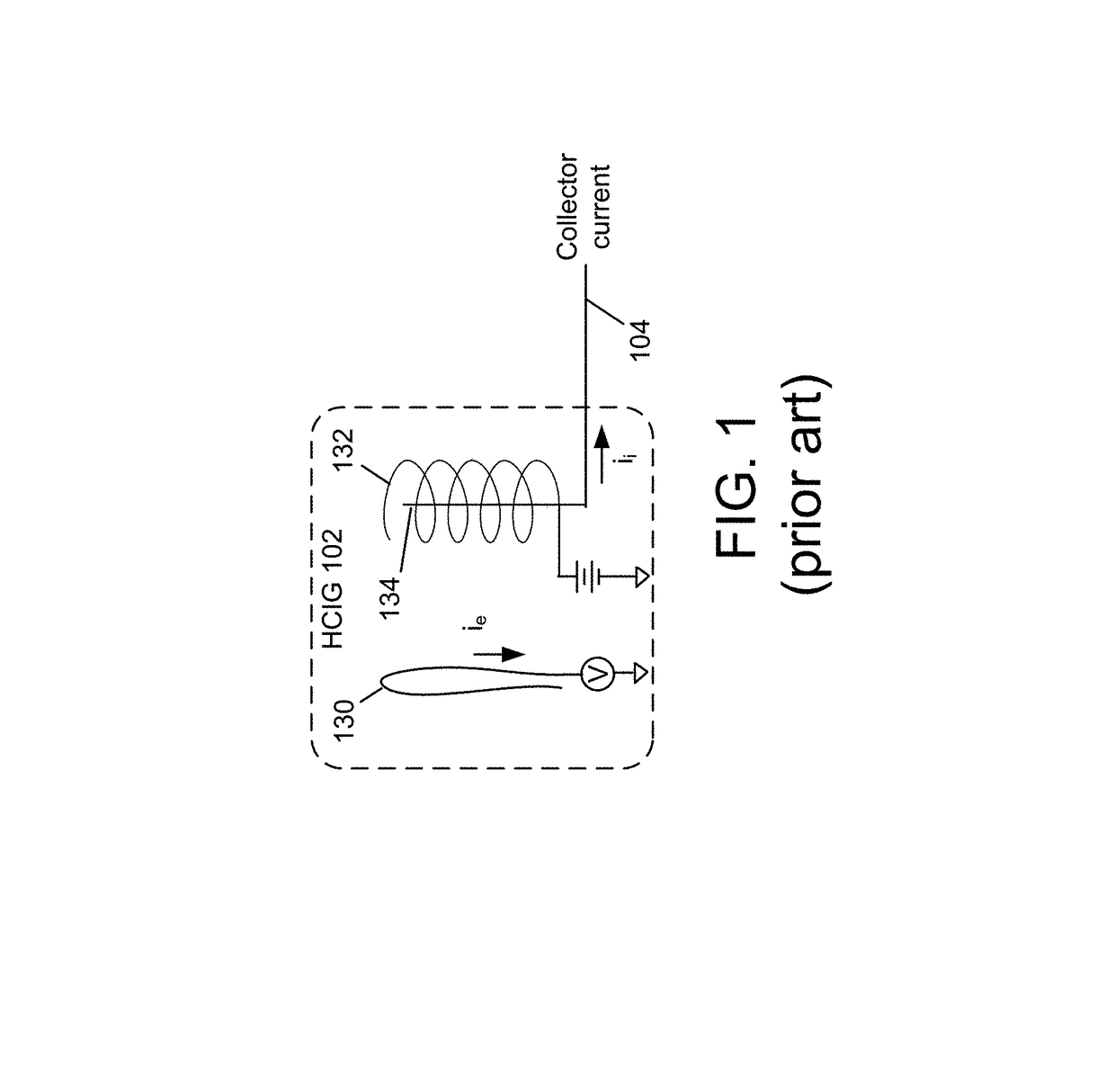
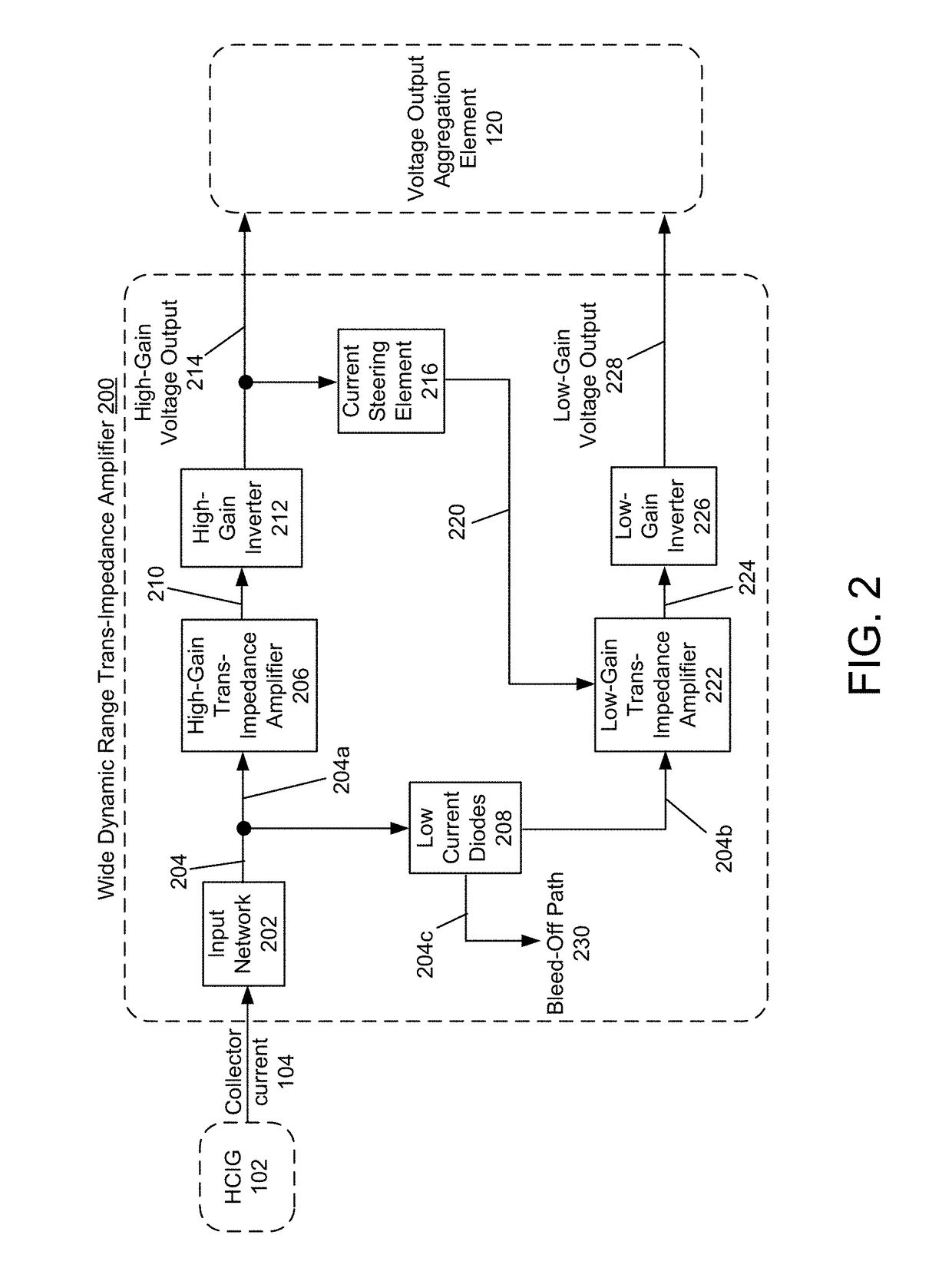
[0042]FIG. 2 illustrates an example embodiment of a wide dynamic range trans-impedance amplifier 200 according to the invention. FIGS. 3 through 9 provide more detail of each of the example block elements of the embodiment shown in FIG. 2. The embodiments presented in FIGS. 3 through 9 are not intended to be limiting, but are rather intended to provide an example description of a specific implementation of the described embodiments.

[0043]Input network 202 receives collector current 104 from HCIG 102 (see also FIG. 1). The input network 202 provides conditioned collector current 204 to a high-gain trans-impedance amplifier 206 and also to a set of low current diodes 208. A first portion of conditioned collector current 204 flows to the high-gain trans-impedance amplifier 206. A second...


PUM


Abstract

A wide dynamic range trans-impedance amplifier includes a first trans-impedance amplifier configured to receive a first input current and produce a first voltage as a function of the first input current, and a second trans-impedance amplifier configured to receive a second input current and produce a second voltage as a function of the second input current. A current steering element causes a first portion of current from a current source to flow to the first trans-impedance amplifier until the first current portion reaches the first threshold current, and causes a second portion of current from the current source to flow to the second trans-impedance amplifier, until the second current portion reaches the second threshold current. The second current portion is current from the current source that exceeds the first threshold current. The wide dynamic range trans-impedance amplifier may receive, for example, ion collector current from a hot cathode ionization gauge (HCIG).

Description

BACKGROUND[0001]Ionization vacuum pressure gauges can be used in a wide variety of applications such as semiconductor manufacturing, thin film deposition, high energy physics, ion implantation, and space simulation. Ionization gauges can include both cold cathode ionization gauges (CCIGs) and hot cathode ionization gauges (HCIGs), and some example HCIG designs include Bayard-Alpert (BA), Schulz-Phelps, and triode gauges.[0002]The sensor of a typical hot cathode ionization vacuum pressure gauge, shown in FIG. 1, includes a cathode 130 (the electron source, also called the filament), an anode 132 (also called the grid), and an ion collector electrode 134. For the BA gauge, the cathode 130 is located radially outside of an ionization space (anode volume) defined by the anode 132.[0003]The ion collector electrode 134 is disposed within the anode volume. Electrons travel from the cathode 130 toward and through the anode 132, and are eventually collected by the anode 132. In their travel,...

Claims


Application Information

Patent Timeline
IPC IPC(8): H03F3/68H03F3/45H03F1/34
CPCH03F3/45H03F1/34H03F2203/45288H03F2203/45161H03F2200/153G01R19/0061H03F1/083H03F1/3211H03F3/45475H03F2200/261H03F2200/462H03F2203/45138H03F2203/45528
Inventor HANSEN, DOUGLAS C.
Owner MKS INSTR INC
Why Eureka
Try Eureka