Left atrial appendage occluder

a technology of appendage occluder and left atrial appendage, which is applied in the field of medical devices, can solve the problems of many limitations of the current left atrial appendage occluder, the deformation of the device, and the irregular shape of the entrance of the left atrial appendag

Active Publication Date: 2017-11-07
LIFETECH SCIENTIFIC (SHENZHEN) CO LTD
View PDF15 Cites 26 Cited by
  • Summary
  • Abstract
  • Description
  • Claims
  • Application Information

AI Technical Summary

Benefits of technology

[0033]1. The left atrial appendage occluder has a stable structure and can fit various structures and various sizes of the cavity of the left atrial appendage to the largest extent.
[0078]2. It is ensured to position on the wall of the left atrial appendage more stably and seal the entrance of the left atrial appendage more closely, considering the balance between the positioning and sealing key effects.
[0079]3. The left atrial appendage occluder is easy to position repeatedly and may be withdrawn before being detached from a conveyor. When in surgical operation, a position area can be selected based on the actual shape and size of the patient's left atrial appendage, selection of an improper position area caused by limitations of the device can be avoided and the surgical risk is lowered.
[0080]4. The operating steps are simple and smooth, so times of repeated positioning by a doctor is reduced to the largest extent, and the damage to a patient is lowered.
[0037]5. The left atrial appendage occluder can fit a small sheath canal, and so the damage of the sheath canal to the patient's vascular wall is lowered.
[0082]The above just describes optimal embodiments of the invention, but is not intended to limit the invention. Any modification, equivalent substitution and improvement made within the spirit and principle of the invention should fall into the protection scope of the invention.

Problems solved by technology

There are many limitations for the current left atrial appendage occluder.
(a) When the device is plugged into the left atrial appendage, the deformability of this device is limited, and the shape of the entrance of the left atrial appendage is very irregular.
Because the entrance of the left atrial appendage cannot be blocked completely, it is difficult to eliminate the thrombus caused by the left atrial appendage due to atrial fibrillation, so that the thrombus endogenus of the “artificial left atrial appendage” device will increase the probability of forming left atrial appendage thrombus.
(b) The anatomical structures of left atrial appendages of all people are in different shapes, such as an oval shape, a peanut shape, etc., and some left atrial appendages have multiple cavities, so the plug type left atrial appendage occluder cannot fit anatomical structures of all left atrial appendages completely and cannot be stably fixed.
(c) Depths of left atrial appendages of all people are different, so the length of the plug type left atrial appendage occluder cannot fit various depths of left atrial appendages.
2. The following shows the limitations of the plug-and-disc type left atrial appendage occluder:
(a) The plug-and-disc type left atrial appendage occluder is a complex body, in which the plug part and the disc part cannot be deformed completely and independently. When the plug is plugged into the left atrial appendage, the shape of the plug needs to comply with the internal structure of the left atrial appendage, so that the disc part will encounter the traction of the plug part when buckled on the entrance of the left atrial appendage. As a result, the disc part cannot fit fully with the entrance of the left atrial appendage. Therefore, the blood flow cannot be blocked completely, and it is difficult to achieve the best occlusion effect.
(b) Because the anatomical structures of left atrial appendages of all people are in different shapes, it is required to find a best fixing point in the cavity of the left atrial appendages. Therefore, it is required that the plug part may realize the best fixation in different depths. However, because the lengths of the plug part and the disc part are limited for adjustment, it is difficult for most left atrial appendages to achieve the best fixation and blockage of blood flow.
3. Furthermore, most part of left atrial appendage occluders plugged in the left atrial appendage is of a closed structure, so the left atrial appendage occluders are difficult to fit different shapes of cavities of left atrial appendages.
4. In addition, it is required to add an anchoring thorn structure on an occluder to fix the left atrial appendage occluder. However, the anchoring thorn structures of present products are unreasonable, for example, the anchoring thorns of some left atrial appendage occluders are several fine wires equipped on the occluders by suture lines. It is difficult for such an anchoring thorn to penetrate through the wall of the left atrial appendage under the condition of compression in the cavity of the left atrial appendage, so that the stable fixation cannot be realized. Besides, the anchoring thorns of some left atrial appendage occluders have enough puncture force but cause an obstacle to the withdrawing of an occluder, so that the occluders cannot realize the repeated positioning.

Method used


Image

  • Left atrial appendage occluder
  • Left atrial appendage occluder
  • Left atrial appendage occluder

Examples


first embodiment

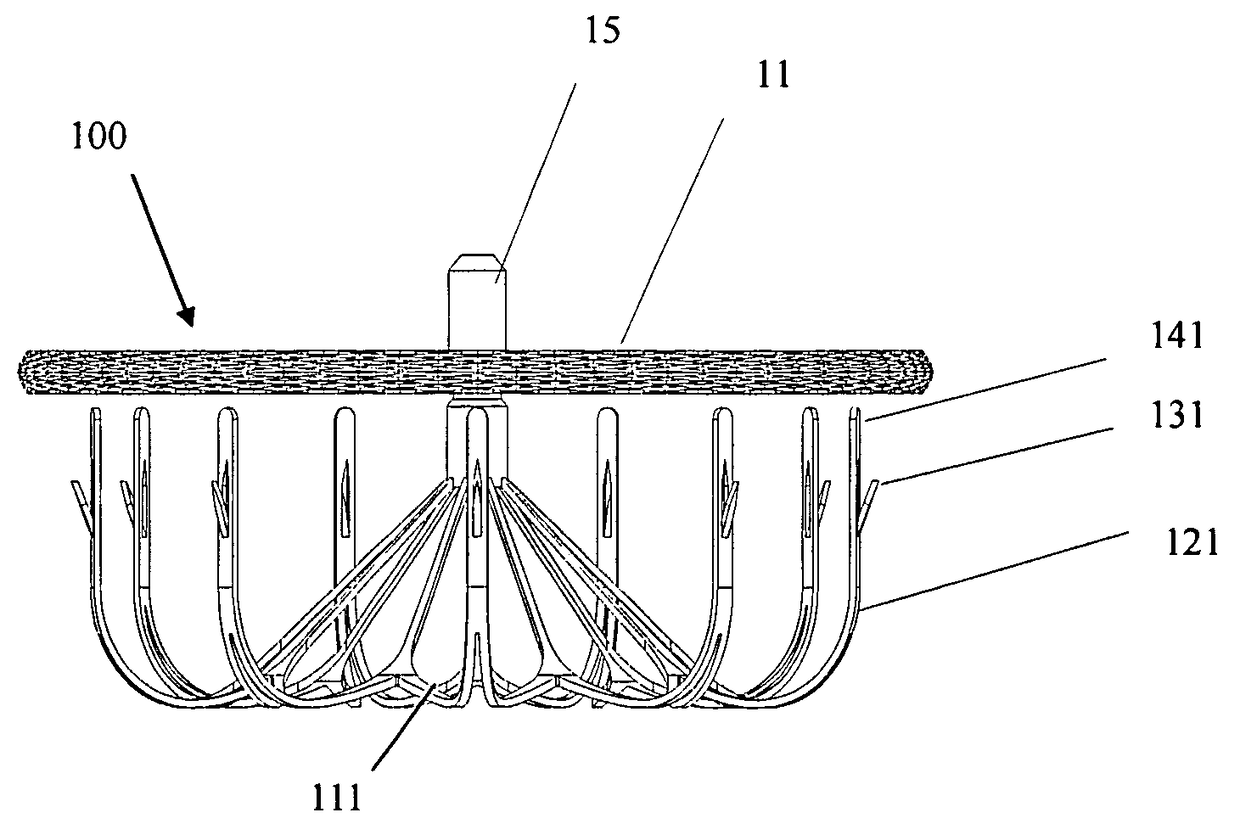
[0067]As shown FIG. 6, FIG. 7 and FIG. 8, the left atrial appendage occluder 100 in the first embodiment of the invention comprises a closure disc 11 and a fixing frame 111 connected with the closure disc 11. Wherein, the fixing frame 111 comprises a plurality of interconnected struts 121. The fixing frame 111 is in a shape as shown in FIG. 6 formed by cutting a nickel titanium tube into a plurality of interconnected struts 121, stretching via a die and then heat treating for shaping. The closure disc 11 is made into a mesh grid 10 via nickel titanium wires by weaving, and then made into a disc shape by heat treatment. Two ends of the closure disc are fixed by sleeves. Then, the sleeve at one end is welded with a connecting member 15 with threads connected with a conveyor, while the other end of the closure disc 11 is a fixed end having its sleeve connected with a connector 16 on the fixing frame 111. Inside the closure disc 11, a flow blocking membrane (PTFE or PET membrane) is sut...

second embodiment

[0068]As shown in FIG. 9, FIG. 10 and FIG. 11, the left atrial appendage occluder 200 in the second embodiment of the invention comprises a closure disc 11 and a fixing frame 112 connected with the closure disc 11. The closure disc 11 is made into a mesh shape via nickel titanium wires by weaving, and then made into a disc shape by heat treatment. Two ends thereof are fixed by sleeves. The sleeve at one end is welded with a connecting member 15 with threads connected with a conveyor. Then, a flow blocking membrane (PTFE or PET membrane) is sutured inside the closure disc 11 via medical suture lines. The other end of the closure disc 11 is a fixed end. The sleeve of the fixed end is connected with a central end of the fixing frame 112. The central end comprises a flexible connector 17. The top view of the closure disc 11 is shown as FIG. 7 in the first embodiment. Struts 122 of the fixing frame 112 are formed by cutting nickel titanium tubes and heat treating them for shaping. During...

third embodiment

[0069]As shown in FIG. 12 to FIG. 15, the left atrial appendage occluder 300 in the third embodiment of the invention comprises a closure disc 11 and a fixing frame 113 connected with the closure disc 11. The closure disc 11 is made into a mesh shape via nickel titanium wires by weaving, and then made into a disc shape by heat treatment. Two ends thereof are fixed by sleeves. The sleeve at one end is welded with a connecting member 15 with threads connected with a conveyor. Then, a flow blocking membrane (PTFE or PET membrane) is sutured inside the closure disc 11 via medical suture lines. The other end of the closure disc 11 is a fixed end. The sleeve of the fixed end is connected with a central end of the fixing frame 113. The central end comprises a connecting spring 18. The top view of the closure disc 11 is shown as FIG. 7 in the first embodiment. Struts 123 of the fixing frame 113 are shaped by cutting and heat treating nickel titanium tubes. Tail ends of the struts 123 are ma...


PUM


Abstract

The present invention relates to a Left atrial appendage occluder comprising an elastic closure disc. The left atrial appendage occluder also comprises an elastic fixing frame connected with the closure disc and located on one side of the closure disc. The fixing frame comprises a central end connected with the closure disc and a plurality of interconnected and bent struts, wherein at least one anchor is set near the end of at least one strut with the anchor pointing toward the closure disc. The left atrial appendage occluder has a stable structure, a good positioning and sealing effect on the cavity wall in the left atrial appendage, and it is easy to position repeatedly; it can also be recycled before separating from a conveyor. When in surgical operation, the left atrial appendage occluder can select the position area based on the actual shape and size of the patient's left atrial appendage, so the surgical risk is lowered.

Description

TECHNICAL FIELD[0001]The invention relates to a medical device, and particularly relates to an occluder which is transmitted to a selected part of a human body by an interventional method through catheter technology to prevent stroke symptoms caused by thrombus resulted from left atrial appendage due to atrial fibrillation.BACKGROUND OF THE INVENTION[0002]Treating diseases by using the interventional method through catheter technology is a therapy applied more and more widely at present. Various materials, devices and medicines are placed into heart and arteriovenous vessels of a human body by the catheter-based interventional therapy.[0003]For example, an occluder (such as, atrial septal defect (ASD) occluder, ventricular septal defect (VSD) occluder, patent ductus arteriosus (PDA) occluder, patent foramen ovale (PFO) occluder, etc.) is placed to a defect part of the heart by the catheter-based interventional method to occlude the defect so as to treat the congenital heart disease....

Claims


Application Information

Patent Timeline
Patent Type & Authority Patents(United States)
IPC IPC(8): A61B17/12A61B17/00
CPCA61B17/12122A61B17/12172A61B17/12177A61B2017/1205A61B2017/00606A61B2017/00619A61B2017/00623A61B2017/00597
Inventor LI, ANNINGZHANG, DEYUAN
Owner LIFETECH SCIENTIFIC (SHENZHEN) CO LTD
Why Eureka
Try Eureka