High dose output, through transmission target X-ray system and methods of use

a high-dose output and target x-ray technology, applied in vacuum tube vessels/containers/shields, radiation generation arrangements, applications, etc., can solve the problem of watt density loading of target anodes before melting, limited utilization of generated x-ray photons, and the symmetry of the resulting radiation field cannot be resolved in the traditional tube design

Active Publication Date: 2017-11-14
RAD SOURCE TECH
View PDF12 Cites 8 Cited by
  • Summary
  • Abstract
  • Description
  • Claims
  • Application Information

AI Technical Summary

Benefits of technology

[0007]Briefly described, in example embodiment, the present apparatus overcomes the above-mentioned disadvantage, and meets the recognized need for a high dose output, through transmission target X-ray tube and methods of use including, in general, an X-ray tube for accelerating electrons under a high voltage potential, said X-ray tube includes an evacuated housing that is sealed, a through transmission target anode structure disposed on said housing, said anode structure configured in a hemispherical shape having a geometric center, a cathode structure disposed in said housing, said cathode configured to deflect the electrons toward said hemispherical anode, a filament disposed in said housing, said filament positioned proximate said geometric center of said hemispherical shape and between said anode and said cathode, an evacuated housing, said housing configured to vacuum seal there in said anode, said cathode, and said filament, and, thus, such X-ray tube functions to provide a large surface area anode target to dissipate heat and to enable use of different z materials to take advantage of the characteristic X-ray with improved radiation output, lower melting point, and lower electrode potential required to produce higher output radiation.
[0012]Still another feature of the high dose output, through transmission target X-ray tube and methods of use is its ability to enable use of a different z material to take advantage of the characteristic X-ray which will increase radiation output.
[0015]Yet another feature of the high dose output, through transmission target X-ray tube and methods of use is its ability to provide a new anode configuration which makes possible the use of alternate target materials having different characteristic X-rays.
[0016]Yet another feature the high dose output, through transmission target X-ray tube and methods of use is its ability to provide X-ray tube that requires no or limited heat dissipation in the form of air cooling or liquid cooling. Moreover, forced air cooling is thus more effective because of the increased surface area of the new anode configuration.
[0018]Yet another feature of the high dose output, through transmission target X-ray tube and methods of use is its ability to provide a new structure and geometry for the anode to increase the surface area of the anode.
[0019]Yet another feature of the high dose output, through transmission target X-ray tube and methods of use is its ability to provide an anode configuration with better heat transfer characteristics which would enable the anode to operate at a lower temperature, and thus enable a lower melting point material choice with improved radiation output and extend the operational life of the X-ray tube.

Problems solved by technology

The primary limitation of this type of tube is the watt density loading of the target anode before melting occurs, limited utilization of generated X-ray photons and the symmetry of the resulting radiation field.
The two requirements are contrary and cannot be resolved in the traditional tube design.
In addition the reflective nature of the emitted radiation is asymmetrical about a beam centerline and is grossly inefficient for X-ray irradiation applications.

Method used


Image

  • High dose output, through transmission target X-ray system and methods of use
  • High dose output, through transmission target X-ray system and methods of use
  • High dose output, through transmission target X-ray system and methods of use

Examples


Embodiment Construction

[0038]In describing the exemplary embodiments of the present disclosure, as illustrated in FIGS. 1-9 specific terminology is employed for the sake of clarity. The present disclosure, however, is not intended to be limited to the specific terminology so selected, and it is to be understood that each specific element includes all technical equivalents that operate in a similar manner to accomplish similar functions. The examples set forth herein are non-limiting examples, and are merely examples among other possible examples.

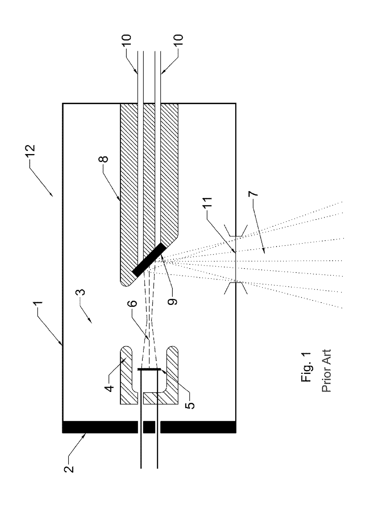
[0039]Referring now to FIG. 1 there is illustrated a schematic cross sectional representation of Coolidge type X-ray tubes 12, shown in FIG. 1, includes X-ray tube housing 1, which may be glass or metal, high voltage insulation 2, and a vacuum dielectric 3 contained therein X-ray tube housing 1. In a Coolidge tube X-ray photons, shown as a fanned output radiation pattern 7, are generated by impinging an electron beam emanating from filament 5, shown as electron tr...


PUM


Abstract

A high dose output, through transmission target X-ray tube and methods of use includes, in general an X-ray tube for accelerating electrons under a high voltage potential having an evacuated high voltage housing, a hemispherical shaped through transmission target anode disposed in said housing, a cathode structure to deflect the electrons toward the hemispherical anode disposed in said housing, a filament located in the geometric center of the anode hemisphere disposed in said housing, a power supply connected to said cathode to provide accelerating voltage to the electrons.

Description

TECHNICAL FIELD[0001]The disclosure relates generally to X-ray tube technology and more specifically it relates to X-ray tubes with specific anode, cathode, filament configurations and material choices to produce high dose X-ray output.BACKGROUND[0002]In many typical state of the art X-ray tubes, a cathode assembly and an anode assembly are vacuum sealed in a glass or metal envelope. Electrons are generated by at least one cathode filament in the cathode assembly. These electrons are accelerated toward the anode assembly by a high voltage electrical field. The high energy electrons generate X-rays upon impact with the anode assembly. A by-product of this process is the generation of substantial amounts of heat.[0003]Traditional X-ray tube configurations are known in the prior art, for example, Coolidge type X-ray tubes. In a Coolidge tube X-ray photons, shown as a spot output radiation pattern, are generated by impinging an electron beam emanating from filament onto the surface of a...

Claims


Application Information

Patent Timeline
Patent Type & Authority Patents(United States)
IPC IPC(8): H01J35/32H01J35/08H01J35/18H01J37/06H01J37/063H01J1/40H01J1/16H01J19/48H01J19/32H01J19/57H01J35/16H01J1/94A61B6/00H01J35/06
CPCH01J19/32H01J1/40H01J19/48H01J35/08H01J35/18H01J35/32H01J37/063H01J1/16H01J2893/0012A61B6/40A61B6/482H01J1/94H01J19/57H01J35/06H01J35/16H01J2235/087H01J2235/186H01J2893/0006H01J35/066H01J35/116H01J35/186
Inventor AUSBURN, PHILLIP KENT
Owner RAD SOURCE TECH
Why Eureka
Try Eureka