System for cooling hybrid vehicle electronics, method for cooling hybrid vehicle electronics

a hybrid vehicle and electronic technology, applied in the direction of machines/engines, mechanical/solid-state device details, machines/engines, etc., can solve the problems of reducing the available space for other components, reducing the cooling rate of vehicles, and not being able to achieve the 105° c. coolant used in standard radiators, etc., to achieve the effect of reducing costs and weight, reducing pumping power, and increasing cooling ra

Active Publication Date: 2017-11-21
UCHICAGO ARGONNE LLC
View PDF4 Cites 6 Cited by
  • Summary
  • Abstract
  • Description
  • Claims
  • Application Information

AI Technical Summary

Benefits of technology

[0014]Another object of the invention is to provide a system and method for cooling hybrid vehicle electronics. A feature of the invention is that only one radiator is required to cool both the internal combustion engine and the electronics of the vehicle. Another feature of the invention is that the invention can be configured to cool a single surface, or a plurality of surfaces of the electronics components. An advantage of the invention is that it confers lighter weight and increased compactness.
[0015]Still another object of the present invention is to provide a compact system for cooling hybrid vehicle electronics. A feature of the invention is that it uses most of the same components of typical cooling systems. An advantage of the invention is that it provides increased cooling rates at low pumping power, therefore leading to reduced costs and weight.
[0016]Yet another object of the present invention is to provide a method for cooling wide-bandgap semiconductor electronics. A feature of the invention is that it eliminates the need for cooling fins, otherwise in thermal communication with the electronics and foundation plates. An advantage of the present invention is its ability to accommodate power densities of at least about 100 W / cm2 without cooling fins and as high as about 250 W / cm2 with fins (multiple-sided cooling), therefore finding applicability to new hybrid electric vehicles with, and without, wide-band semiconductors.
[0017]Another object of the present invention is to provide approximately a 25 percent more efficient method and system for cooling high power electronics. For example, the present invention can optimize a current, one-sided, cooling system from a typical 100 W / cm2 power density to 125. A feature of the invention is the use of traditional vehicle coolants that are subcooled, such that the coolants remain as substantially a single phase throughout the cooling cycle. An advantage of the invented boiling coolant method and system is its superior heat removal capacity compared to traditional laminar fluid flow convective heat transfer systems, such that the invented system facilitates more efficient cooling of high power density electronics.
[0018]Still another object of the present invention is to provide a single radiator system that combines internal combustion engine cooling and power electronics cooling operations, whereby the system can maintain 250 W / cm2 density electronics at or below 175° C. A feature of the invention is that a plurality of typical electronic heat sink surfaces (e.g. two sides of a semiconductor chip) are contacted with pressurized typical engine coolant. An advantage of the invention is that the pressurized fluid provides an adequate subcooling temperature range for keeping junction temperatures of advanced power electronics within operating limits. The system is passive in that it does not require cooling jets, nozzles, gas separators or other moving means for cooling heated surfaces via atomization (e.g. spray cooling), forced convection (e.g. pressurized), or other mechanical means of mass flow of a fluid such as liquid coolant or gas such as air or refrigerant. Rather, the engine coolant's resistance to heat transfer is substantially decreased by the subcooled boiling. As such, an embodiment of the invention is nozzle-less.
[0019]Briefly, the invention provides a single radiator cooling system for use in hybrid electric vehicles, the system comprising a surface in thermal communication with electronics, and subcooled boiling fluid contacting the surface.

Problems solved by technology

This cannot be accomplished with 105° C. coolant used in standard radiators.
This second radiator and associated plumping adds cost and weight to the vehicle while reducing available space for other components.

Method used


Image

  • System for cooling hybrid vehicle electronics, method for cooling hybrid vehicle electronics
  • System for cooling hybrid vehicle electronics, method for cooling hybrid vehicle electronics
  • System for cooling hybrid vehicle electronics, method for cooling hybrid vehicle electronics

Examples


example

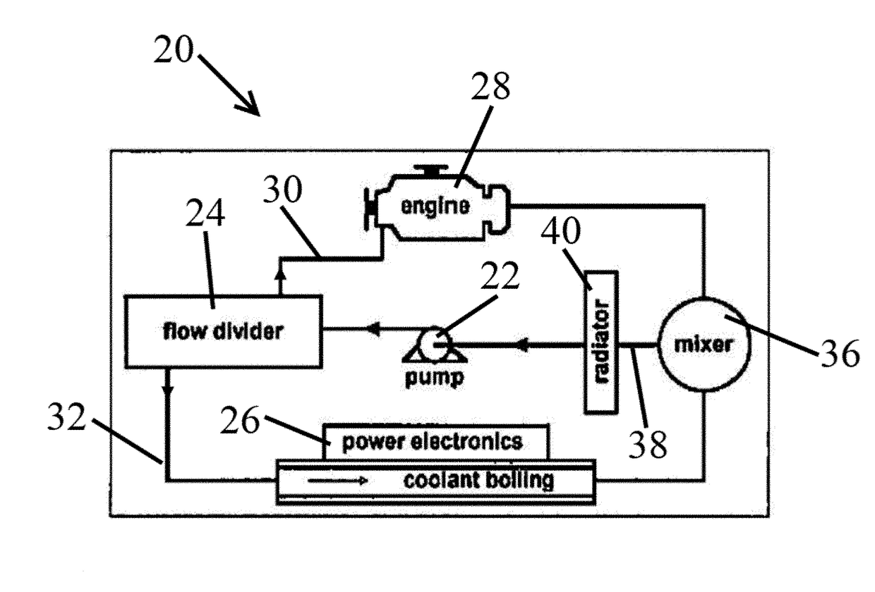
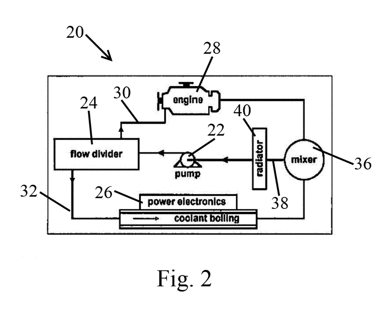
[0055]As noted supra, an embodiment of the invented system and method utilizes typical anti-freeze, anti-boil fluids found in internal combustion engine paradigms. The main engine cooling system works at about 2 atm absolute or 1 atm gauge (approximately 15 psig) of pressure. A corresponding saturation temperature for the 50 / 50 ethylene glycol / water mixture is about 129° C. Simulations show that there is enough of a subcooled range for keeping the juncture temperature of power electronics within the preferred aforementioned 150-175° C. window.

[0056]Simulations by the inventors revealed the conditions under which the coolant exits the power electronic channels and is still be below the saturation point. Exemplary conditions include the following:[0057]Because the subcooled boiling system is integrated into the main engine cooling system, the conventional engine coolant, a 50 / 50 EG / W mixture, is used for power electronics cooling.[0058]The pressure in the cooling channel for power ele...


PUM


Abstract

The invention provides a single radiator cooling system for use in hybrid electric vehicles, the system comprising a surface in thermal communication with electronics, and subcooled boiling fluid contacting the surface. The invention also provides a single radiator method for simultaneously cooling electronics and an internal combustion engine in a hybrid electric vehicle, the method comprising separating a coolant fluid into a first portion and a second portion; directing the first portion to the electronics and the second portion to the internal combustion engine for a time sufficient to maintain the temperature of the electronics at or below 175° C.; combining the first and second portion to reestablish the coolant fluid; and treating the reestablished coolant fluid to the single radiator for a time sufficient to decrease the temperature of the reestablished coolant fluid to the temperature it had before separation.

Description

CONTRACTUAL ORIGIN OF THE INVENTION[0001]The U.S. Government has rights in this invention pursuant to Contract No. DE-AC02-06CH11357 between the U.S. Department of Energy and UChicago Argonne, LLC, representing Argonne National Laboratory.BACKGROUND OF THE INVENTION[0002]1. Field of the Invention[0003]This invention relates to a system for cooling electronics, and more specifically this invention relates to a compact system and method for cooling hybrid vehicle electronics using only one radiator.[0004]2. Background of the Invention[0005]Hybrid vehicle electronics have become more sophisticated. As a result, the use of wide-bandgap semiconductors will increase. Wide-bandgap semiconductors permit devices to operate at much higher voltages, frequencies and temperatures than conventional semiconductor materials. This allows for more powerful electrical mechanisms to be built which are cheaper and more energy efficient.[0006]“Wide-bandgap” refers to higher voltage electronic band gaps s...

Claims


Application Information

Patent Timeline
Patent Type & Authority Patents(United States)
IPC IPC(8): B60K11/00H01L23/427H01L23/473H05K7/20H01L23/36F01P3/00
CPCH05K7/20945H01L23/36H01L23/427H05K7/20936H01L23/473F01P2050/24F01P2003/008F01P3/2285F01P7/165
Inventor FRANCE, DAVID M.YU, WENHUASINGH, DILEEPZHAO, WEIHUAN
Owner UCHICAGO ARGONNE LLC
Why Eureka
Try Eureka