
Method and system for diagnosing efficiency of an aftertreatment system of an internal combustion engine

Inactive Publication Date: 2017-12-05
GM GLOBAL TECH OPERATIONS LLC
View PDF2 Cites 1 Cited by
  • Summary
  • Abstract
  • Description
  • Claims
  • Application Information

AI Technical Summary

Benefits of technology

The patent provides a system and method for identifying when an oxidation catalyst cannot support the regeneration process of a particulate filter. This allows for the adoption of measures to prevent these side effects in a simple and cost-effective way.

Problems solved by technology

However, during the lifetime of the Diesel oxidation catalyst, the conversion efficiency of this component is not constant but decreases progressively due to ageing and / or poisoning effects.
For this reason, it may happen that the conversion efficiency of the Diesel oxidation catalyst reaches a level which still allows this component to reduce the polluting emissions during the normal operation of the engine, but makes it unsuitable to efficiently oxidize the post injected fuel quantities during the regeneration process of the Diesel particulate filter.
As a consequence, these post injected fuel quantities may exit unburnt from the Diesel oxidation catalyst and be ignited just inside the Diesel particulate filter, due to precious metals contained in its wash coat, thereby increasing the thermal stress of this component and of other neighboring components of the motor vehicle, such as the vehicle under hood and underfloor.

Method used


Image

  • Method and system for diagnosing efficiency of an aftertreatment system of an internal combustion engine
  • Method and system for diagnosing efficiency of an aftertreatment system of an internal combustion engine
  • Method and system for diagnosing efficiency of an aftertreatment system of an internal combustion engine

Examples


Embodiment Construction

[0044]The following detailed description is merely exemplary in nature and is not intended to limit the invention or the application and uses of the invention. Furthermore, there is no intention to be bound by any theory presented in the preceding background of the invention or the following detailed description.

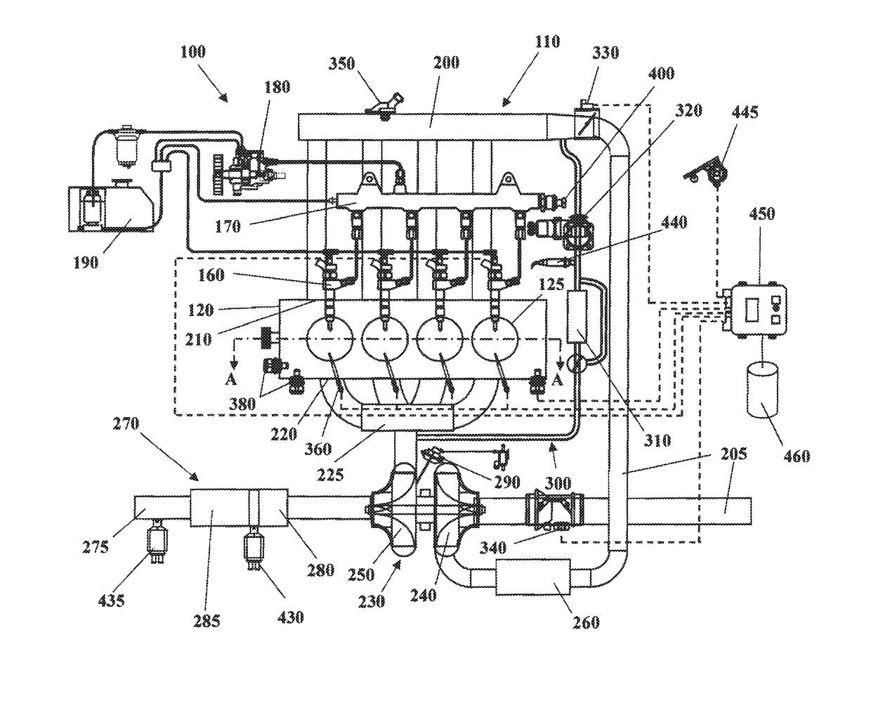
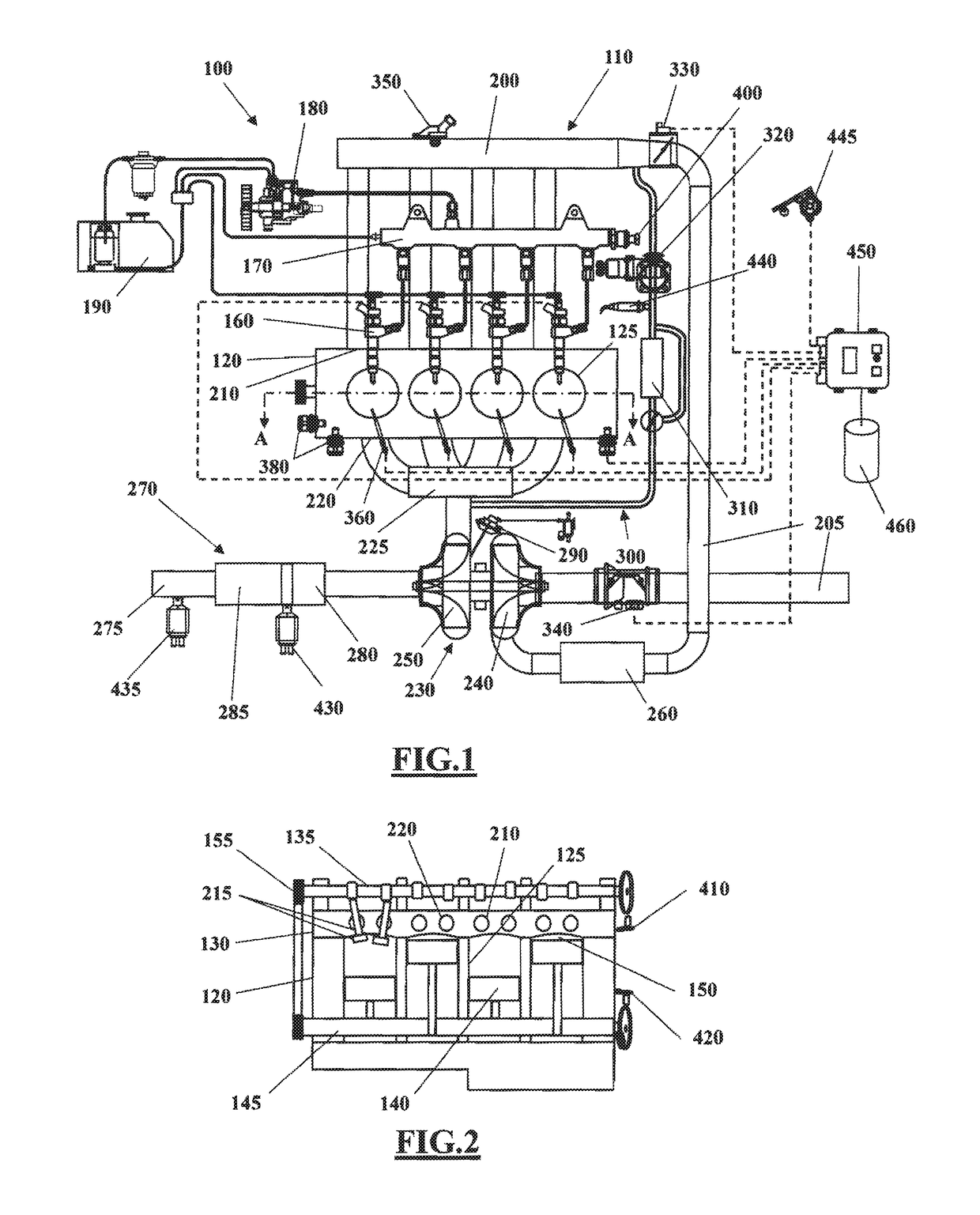
[0045]Some embodiments may include an automotive system 100 (e.g. a motor vehicle), as shown in FIGS. 1 and 2, that includes an internal combustion engine (ICE) 110 having an engine block 120 defining at least one cylinder 125 having a piston 140 coupled to rotate a crankshaft 145. A cylinder head 130 cooperates with the piston 140 to define a combustion chamber 150. A fuel and air mixture (not shown) is disposed in the combustion chamber 150 and ignited, resulting in hot expanding exhaust gasses causing reciprocal movement of the piston 140. The fuel is provided by at least one fuel injector 160 and the air through at least one intake port 210. The fuel is provided at high ...


PUM


Abstract

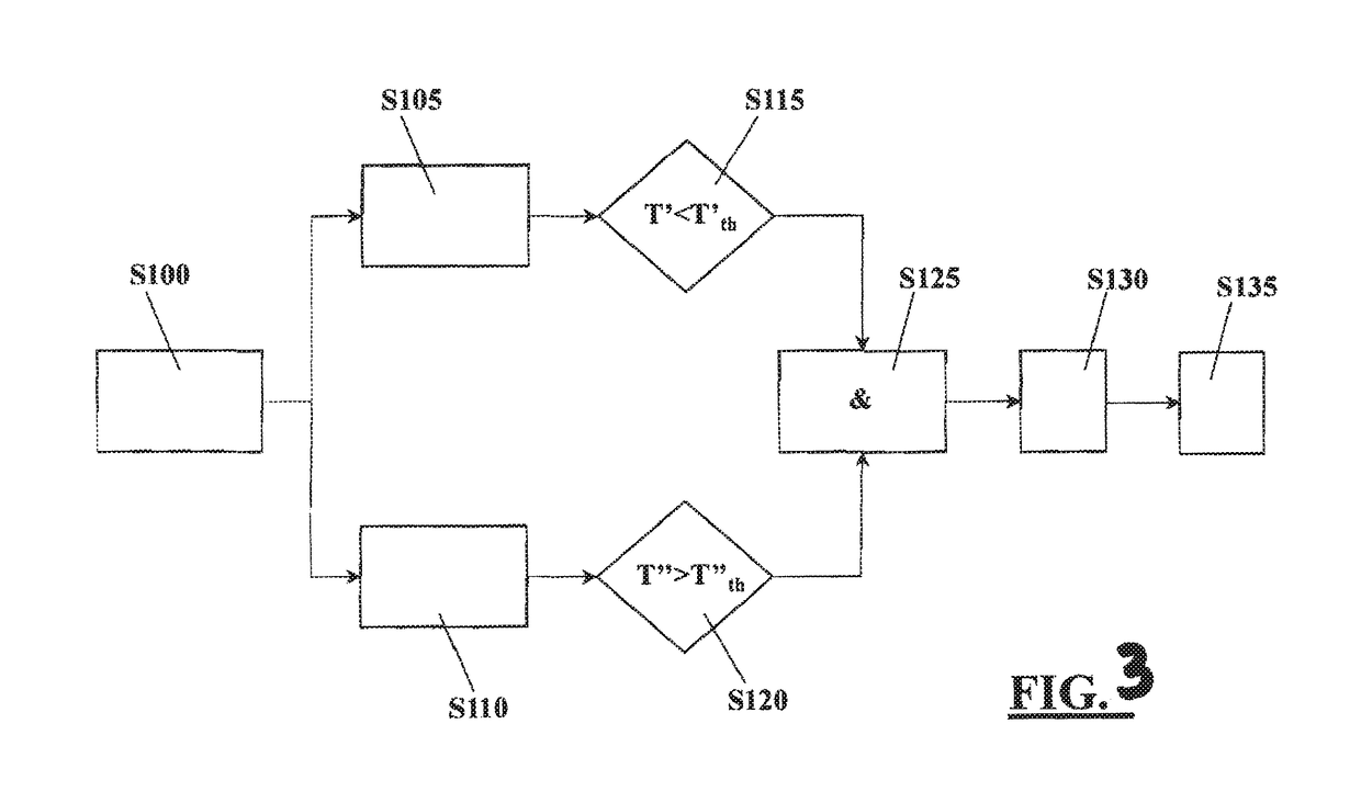
An aftertreatment system for an internal combustion system includes an exhaust duct, an oxidation catalyst disposed in the exhaust duct and a particulate filter disposed in the exhaust duct downstream of the oxidation catalyst. The internal combustion engine is operated to perform a regeneration process of the particulate filter. A first value of exhaust gas temperature in the exhaust duct between the oxidation catalyst and the particulate filter is determined. A second value of exhaust gas temperature in the exhaust duct downstream of the particulate filter is determined. A malfunctioning of the oxidation catalyst is determined when the first value of exhaust gas temperature is below a first predetermined threshold value thereof and contemporaneously the second value of exhaust gas temperature is above a second predetermined threshold value thereof during the regeneration process.

Description

CROSS-REFERENCE TO RELATED APPLICATION[0001]This application claims priority to Great Britain Patent Application No. 1505703.7, filed Apr. 1, 2015, which is incorporated herein by reference in its entirety.TECHNICAL FIELD[0002]The present disclosure pertains to a method and a system for diagnosing efficiency of an aftertreatment system of an internal combustion engine, such as a Diesel engine of a motor vehicle.BACKGROUND[0003]It is known that an internal combustion engine of a motor vehicle is equipped with an aftertreatment system designed to change the composition of the exhaust gas in order to reduce the pollutant emissions. Some aftertreatment systems may include a catalytic converter, for example a Diesel oxidation catalyst (DOC), followed by a particulate filter, for example a Diesel particulate filter (DPF). A Diesel oxidation catalyst usually comprises a catalyst substrate (core), for example a ceramic monolith with a honeycomb structure, which supports a wash coat that car...

Claims


Application Information

Patent Timeline
IPC IPC(8): F01N11/00F01N13/00F01N3/023F01N3/10
CPCF01N3/023F01N3/106F01N11/002F01N13/009F01N3/103Y02T10/47F01N2550/02F01N2560/06F01N2560/14F01N2610/03F01N2900/1404F01N2430/085F01N3/025F01N3/035F01N11/00Y02T10/40F01N9/002
Inventor CASSANI, STEFANOCARMINATI, PAOLO FRANCESCOSACCO, NICOLA PIO
Owner GM GLOBAL TECH OPERATIONS LLC
Learn More