Radiation image detecting device

a detection device and radiation image technology, applied in the field of radiation image detection devices, can solve the problems of increasing the probability of erroneous judgment on whether or not x-ray irradiation has been started naturally, generating random noise, and increasing the difficulty of detecting the probability of x-ray irradiation starting naturally, etc., and achieve the effect of more accurate detection of radiation irradiation

Inactive Publication Date: 2017-12-26
FUJIFILM CORP
View PDF7 Cites 10 Cited by
  • Summary
  • Abstract
  • Description
  • Claims
  • Application Information

AI Technical Summary

Benefits of technology

[0014]In view of the foregoing, an object of the present invention is to provide a radiation image detecting device capable of judging whether or not radiation irradiation has been started more accurately.

Problems solved by technology

It is known that random noise is generated in an analog signal processing circuit for reading out a dose signal.
The problem becomes more serious as the sampling period is made shorter for the purpose of ensuring promptness in the judgment on whether or not the X-ray irradiation has been started.
In the case where the judgment on whether or not the X-ray irradiation has been started is made in a state that the S / N ratio of the dose signal is poor, the probability of erroneous judgment on whether or not the X-ray irradiation has been started naturally becomes high.

Method used


Image

  • Radiation image detecting device
  • Radiation image detecting device
  • Radiation image detecting device

Examples


first embodiment

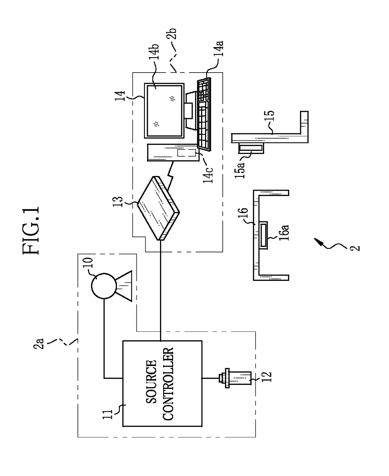
[0040]In FIG. 1, an X-ray imaging system 2 of the present invention includes an X-ray source 10, a source controller 11 for controlling operation of the X-ray source 10, an irradiation switch 12 for giving a command to start warming-up and X-ray irradiation to the X-ray source 10, an electronic cassette 13 having a function of judging whether or not radiation irradiation has been started and an automatic exposure control (AEC) function of stopping the radiation irradiation when an accumulated dose of radiation reaches a target dose so as to detect X-rays having passed through an object (i.e. patient) and output an X-ray image, a console 14 for performing operation control of the electronic cassette 13 and performing display processing of the X-ray images, an upright-posture imaging table 15 for imaging the object in a standing posture, and a supine-posture imaging table 16 for imaging the object in a lying posture. The X-ray source 10, the source controller 11, and the irradiation s...

second embodiment

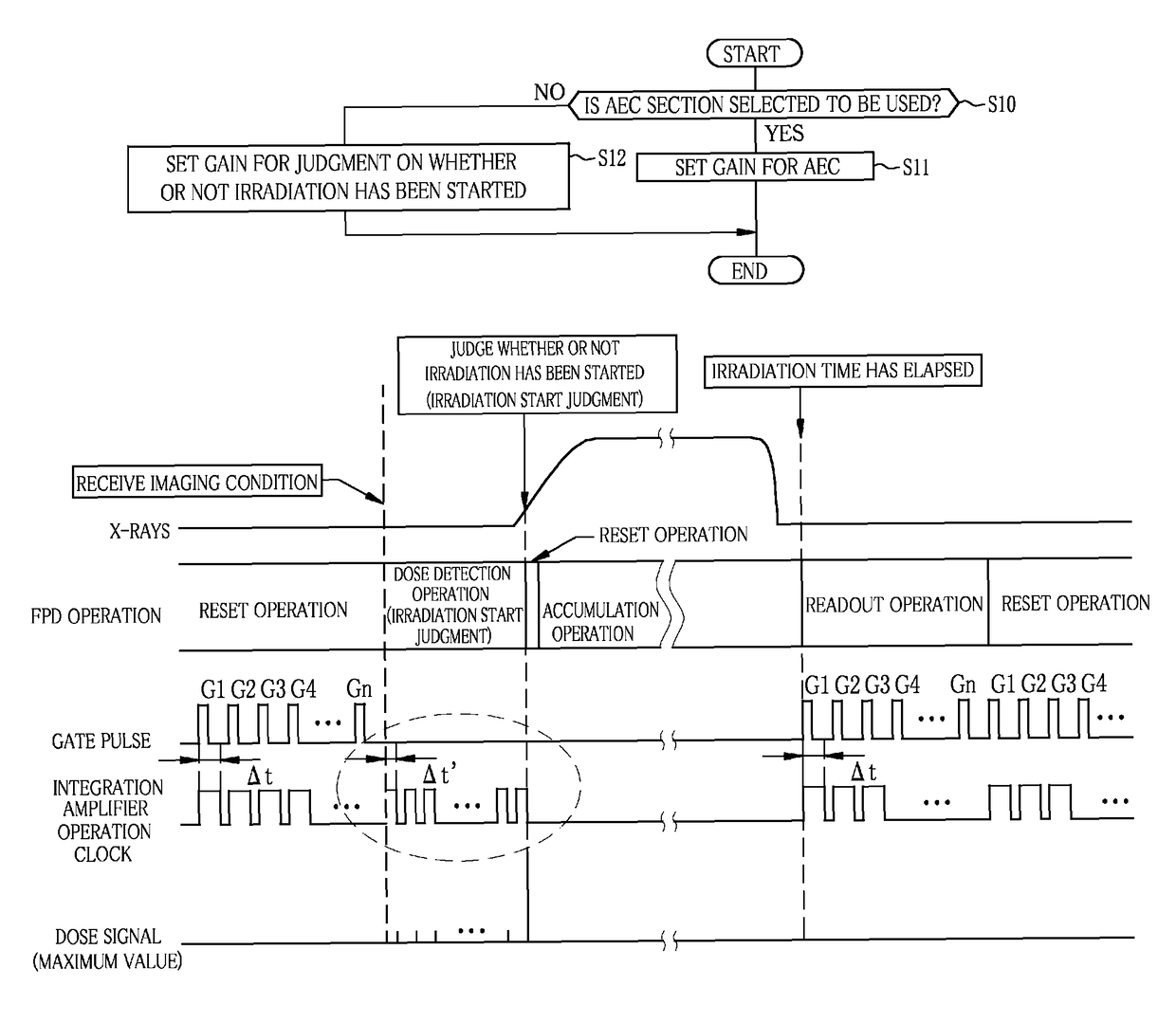
[0113]According to the first embodiment, in both of the case where the irradiation start judging section 62 is used and the case where the AEC section 63 is used, the sampling period of the dose signal is set to Δt, which is the same as that at the time of performing the readout operation. However, the sampling period at the time of using the irradiation start judging section 62 may be different from the sampling period at the time of using the AEC section 63.

[0114]Specifically, as shown in FIG. 10, the sampling period of the dose signal in the case of using the irradiation start judging section 62 is set to Δt′ which is shorter than Δt used in the first embodiment. The length of Δt′ is half of the length of Δt, for example. The control unit 48 controls operation of the respective components of the signal processing circuit 47 such that the sampling period is set to Δt′ in the case of using the irradiation start judging section 62 and the sampling period is set to Δt in the case of ...

third embodiment

[0117]Although the TFT 43 of each of the detection pixels 41 has a short between the source electrode and the drain electrode in the first embodiment, the detection pixel may be a pixel in which the TFT 43 is not provided and the photoelectric converter 42 is directly connected to the signal line 45. Alternatively, a detection pixel 41c shown in FIG. 11 may be adopted. Note that, the same components as those in the first embodiment are denoted by the same reference numerals, and the explanation thereof will be omitted.

[0118]In FIG. 11, the sensor panel 90 has the detection pixels 41c, each of which is connected to a TFT 93 driven by a scanning line 91 and a gate driver 92, while the scanning line 91 and the gate driver 92 are respectively different from the scanning line 44 and the gate driver 46 for driving the TFT 43 of the normal pixel 41a. Since each of the detection pixels 41c is connected to the TFT 93, it is possible to read out the electric charges even if the TFTs 43 of the...


PUM


Abstract

A sensor panel of an electronic cassette includes detection pixels each for outputting a dose signal corresponding to a dose of X-rays, an irradiation start judging section for judging whether or not X-ray irradiation has been started based on the dose signal, and an AEC section for judging whether or not an accumulated dose of X-rays has reached a target dose based on the dose signal. A gain setting section sets a gain of an integration amplifier in the case of using the irradiation start judging section lower than that in the case of using the AEC section.

Description

CROSS-REFERENCE TO RELATED APPLICATIONS[0001]This application is a Continuation of PCT International Application No. PCT / JP2013 / 073287 filed on Aug. 30, 2013, which claims priority under 35 U.S.C §119(a) to Japanese Patent Application No. 2012-204239 filed Sep. 18, 2012. The above application is hereby expressly incorporated by reference, in its entirety, into the present application.BACKGROUND OF THE INVENTION[0002]1. Field of the Invention[0003]The present invention relates to a radiation image detecting device for detecting a radiation image.[0004]2. Description Related to the Prior Art[0005]In a medical field, an X-ray imaging system using radiation such as X-rays is known. The X-ray imaging system includes an X-ray generating apparatus for generating X-rays and an X-ray imaging apparatus for acquiring an X-ray image of an object (i.e. patient) from the X-rays having passed through the object. The X-ray generating apparatus includes an X-ray source for irradiating the X-rays to ...

Claims


Application Information

Patent Timeline
Patent Type & Authority Patents(United States)
IPC IPC(8): A61B6/00H04N5/32
CPCA61B6/542A61B6/4283H04N5/32A61B6/544A61B6/4208A61B6/469
Inventor TAJIMA, TAKASHI
Owner FUJIFILM CORP
Why Eureka
Try Eureka