
Shaped product made of fiber-reinforced composite material and having excellent surface appearance

a composite material and fiber reinforcement technology, applied in the field of shaped products, can solve the problems of low corrosion resistance, difficult mold mold, and poor appearance of the member, and achieve the effects of excellent surface appearance, lightening weight and surface appearan

Active Publication Date: 2018-01-02
TEIJIN LTD
View PDF46 Cites 0 Cited by
  • Summary
  • Abstract
  • Description
  • Claims
  • Application Information

AI Technical Summary

Benefits of technology

[0030]According to the present invention, by using a shaped product which is made of a fiber-reinforced composite material including reinforcing fibers and a thermoplastic resin and has an excellent surface appearance such a shaped product may be achieve requirements of lightening weight and surface appearance in various fields such as electrical and electronic equipments, automobiles, medical equipments, aircrafts, building materials, and general industrial parts.
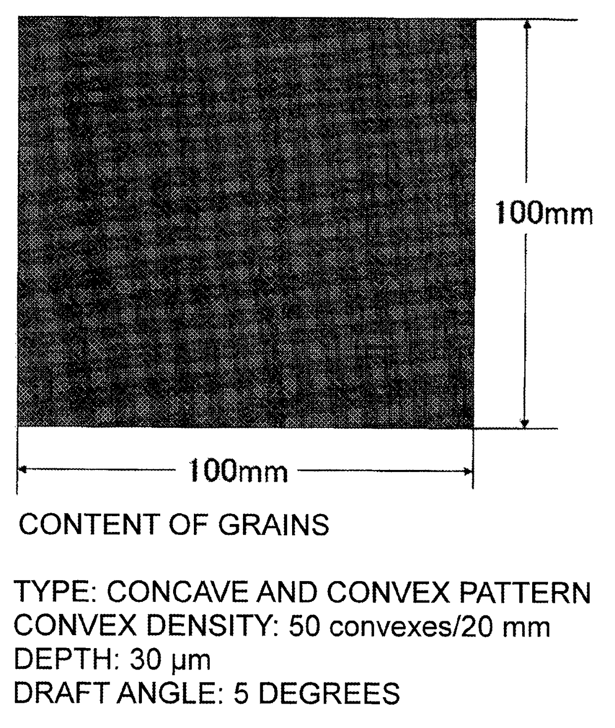
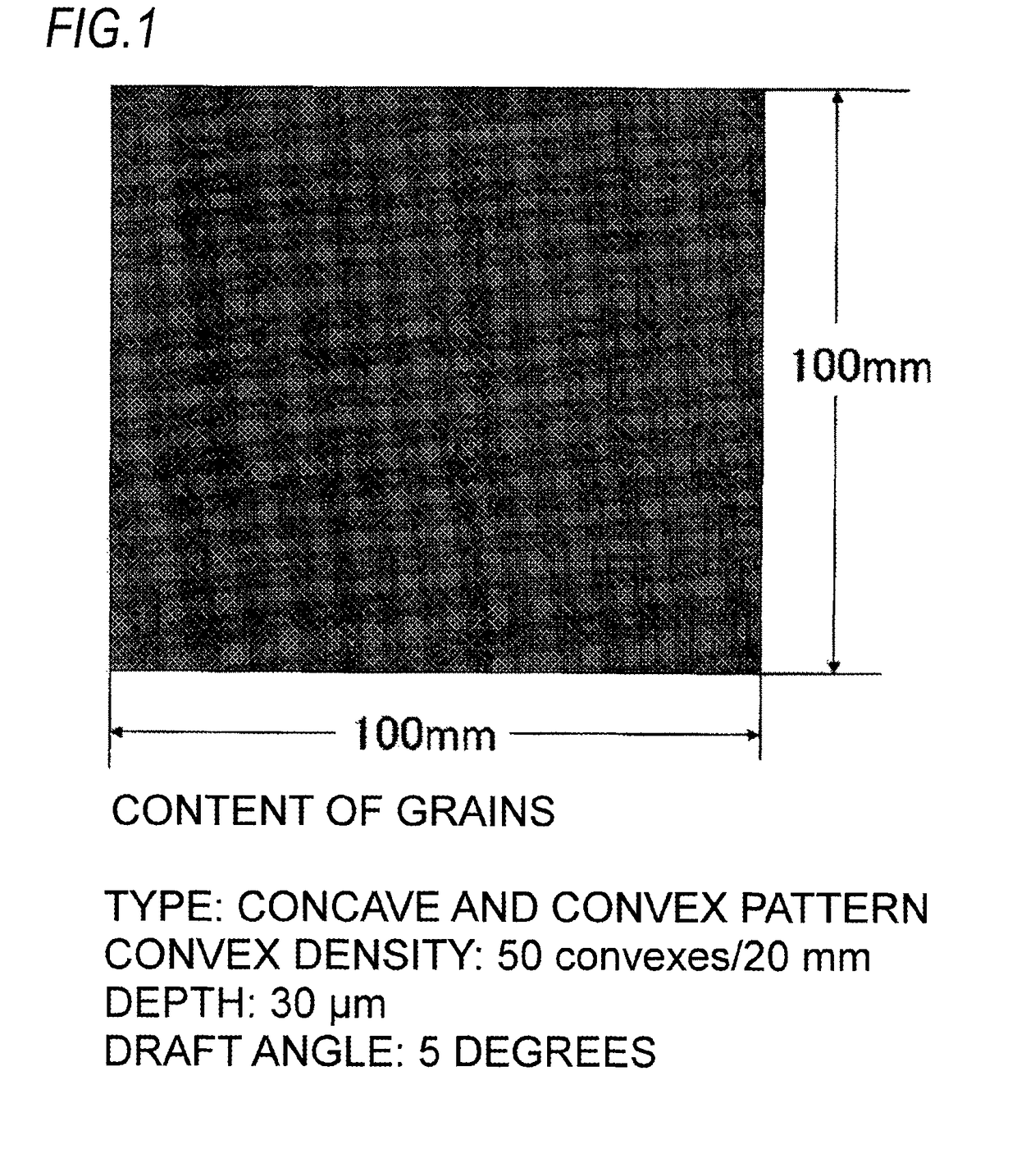
[0031]FIG. 1 is a schematic diagram of a surface including grains having a concave and convex pattern, a convex density of 50 convexes / 20 mm, a depth of 30 μm, and a draft angle of 5 degrees in shaped products obtained through Examples 1, 2, 6 to 10, and Comparative Example 3, and a graining mold including a cavity having a surface to which the grain shape is transferred is used in Examples 1, 2 and 6 to 10 and Comparative Examples 1 to 3.
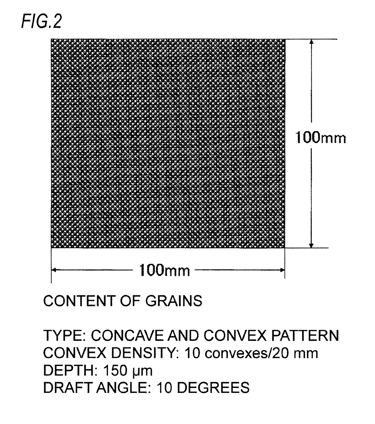
[0032]FIG. 2 is a schematic diagram of a surface including grains having a concave and convex pattern, a convex density of 10 convexes / 20 mm, a depth of 150 μm, and a draft angle of 10 degrees in a shaped product obtained through Example 3, and a graining mold including a cavity having a surface to which the grain shape is transferred is used in Example 3.
[0033]FIG. 3 is a photograph of a surface having leather-like grains of a shaped product obtained through Example 4 (a depth of 225 μm, a draft angle of 23 degrees).
[0034]FIG. 4 is a photograph of a surface having leather-like grains of a shaped product obtained through Example 5 (a depth of 110 μm, a draft angle of 11 degrees).

Problems solved by technology

The aluminum alloy or the magnesium alloy has excellent strength or rigidity, but since there is a limitation of shape formability, it is difficult to mold a complicate shape therewith only.
Further, there is a problem in that a metal member (particularly, a magnesium alloy) has low corrosion resistance, and there is a problem in that a surface is corroded by moisture in the atmosphere or moisture or salts contained in sweat of a user to cause bad appearance of the member.
In this method, it is possible to form a complicate shape and give corrosion resistance, but a process is complicated.
Therefore, there is a limitation in achieving lightening weight.
However, since a length of the fiber included in a shaped article is shortish, the shaped product has still a problem in use requiring high strength or rigidity.
However, since the aforementioned fiber-reinforced composite material is low flexibility in shape in comparison to a resin, or a fiber-reinforced composite material through injection-molding, it is difficult to mold a complicate shape with a simple substance.
Furthermore, there is a problem in that since the fiber-reinforced composite material is manufactured by layering the reinforcing fibers in a woven fabric form in multiple layers, productivity is low.
However, since the shaped product is manufactured through multiple processes, productivity may be not high.
However, even in the RTM molding method, since it takes a time of 10 minutes or more to mold one part, productivity is not improved.
However, the fiber-reinforced composite material manufactured using the thermoplastic resin as a matrix is now being studied and developed, and a technology for obtaining a shaped product having an excellent surface appearance and a quality endurable to practical use by molding the fiber-reinforced composite material has not been sufficiently established.

Method used


Image

  • Shaped product made of fiber-reinforced composite material and having excellent surface appearance
  • Shaped product made of fiber-reinforced composite material and having excellent surface appearance
  • Shaped product made of fiber-reinforced composite material and having excellent surface appearance

Examples


reference example 1

[0179]Carbon fibers (Tenax (registered trade mark) STS40-24KS (average fiber diameter: 7 μm, strand width: 10 mm) manufactured by Toho Tenax Co., Ltd.) were used as reinforcing fibers. The carbon fibers were cut to a length of 10 mm while being widened in a width of 20 mm, and introduced into a taper tube at a supply rate of the carbon fibers of 301 g / min, and while air was blown to the carbon fibers in the taper tube to partially open the fiber bundle, the carbon fibers were sprayed onto a table provided under an outlet of the taper tube.

[0180]In addition, a PA 66 fiber (a polyamide 66 fiber manufactured by Asahi Kasei Fibers Corporation: T5 nylon, fineness: 1400 dtex), which was dry-cut to a length of 2 mm, was supplied as a matrix resin into the taper tube at a rate of 430 g / min, and sprayed together with the carbon fibers. Accordingly, a random mat in which the carbon fibers having an average fiber length of 10 mm and the PA 66 were mixed was obtained. In the random mat, a volum...

reference example 2

[0182]Carbon fibers (Tenax (registered trade mark) IMS60-12K (average fiber diameter: 5 μm, strand width: 6 mm) manufactured by Toho Tenax Co., Ltd.) were used as reinforcing fibers. The carbon fibers were cut to a length of 20 mm, and introduced into a taper tube at a supply rate of the carbon fibers of 1222 g / min, and while air was blown to the carbon fibers in the taper tube to partially open the fiber bundle, the carbon fibers were sprayed onto a table provided under an outlet of the taper tube.

[0183]In addition, a PP resin (polypropylene manufactured by Prime Polymer Co., Ltd: Prime Polypro J108M), which was obtained by freeze-pulverizing into an average particle diameter of about 1 mm, was supplied as a matrix resin into the taper tube at a supply rate of 2527 g / min, and sprayed together with the carbon fibers. Accordingly, a random mat in which the carbon fibers having an average fiber length of 20 mm and the PP were mixed was obtained. In the random mat, a volume fraction ra...

reference example 3

[0185]Glass fibers (EX-2500 (average fiber diameter: 15μm, strand width: 9 mm) manufactured by Nippon Electric Glass Co., Ltd.) were used as reinforcing fibers. The glass fibers were cut to a length of 50 mm, and introduced into a taper tube at a supply rate of the glass fibers of 412 g / min, and while air was blown to the glass fibers in the taper tube to partially open the fiber bundle, the glass fibers were sprayed onto a table provided under an outlet of the taper tube.

[0186]In addition, a PC resin (a polycarbonate resin manufactured by Teijinkasei Co., Ltd: Panlite (registered trade mark) L-1225L), which was obtained by freeze-pulverizing into an average particle diameter of about 710 μm, was supplied as a matrix resin into the taper tube at a supply rate of 791 g / min, and sprayed together with the glass fibers. Accordingly, a random mat in which the glass fibers having an average fiber length of 50 mm and the PC were mixed was obtained. In the random mat, a volume fraction rati...


PUM


Abstract

There is provided a shaped product made of a fiber-reinforced composite material including reinforcing fibers having an average length of 5 mm or more and 100 mm or less and a thermoplastic resin, in which a volume fraction of reinforcing fibers (Vf=100×volume of reinforcing fibers / (volume of reinforcing fibers+volume of thermoplastic resin)) is 5 to 80%, grains are formed on a surface of the shaped product, and a ratio of a reinforcing fiber bundle (A) including the reinforcing fibers of a critical number of single fiber or more, the critical number defined by Formula (1), to the total amount of the reinforcing fibers is 20 Vol % or more and 99 Vol % or less:Critical number of single fiber=600 / D  (1)(wherein D is an average fiber diameter (μm) of single reinforcing fiber).

Description

CROSS-REFERENCE TO RELATED APPLICATIONS[0001]This application is a continuation of PCT International Application No. PCT / JP2012 / 072498, filed on Sep. 4, 2012, which claims priority under 35 U.S.C. §119(a) to Japanese Patent Application No. 2011-193977 filed on Sep. 6, 2011, all of which are hereby expressly incorporated by reference into the present application.TECHNICAL FIELD[0002]The present invention relates to a shaped product which is made of a fiber-reinforced composite material including a reinforcing fiber and a thermoplastic resin and has an excellent surface appearance, and a method for producing the shaped product.BACKGROUND ART[0003]In recent years, there is an increasing need for lightening weight in various fields such as electrical and electronic equipments, automobiles, medical equipments, aircrafts, building materials, and general industrial parts, and housings or parts thereof need to be lightweight and to have high rigidity. As the housings or parts having a thin ...

Claims


Application Information

Patent Timeline
Patent Type & Authority Patents(United States)
IPC IPC(8): B29C45/00B29C70/46B29C70/12C08K7/02C08J5/04B29C43/14C08J5/24B29C43/00B29C33/42B29K101/12B29K105/08B29K105/12
CPCB29C45/0005B29C70/12B29C70/46C08J5/04C08J5/042C08J5/043C08J5/24B29C43/14C08K7/02Y10T428/24405B29C33/424B29C43/003B29K2101/12B29K2105/0854B29K2105/0872B29K2105/12C08J2323/12C08J2367/02C08J2369/00C08J2377/02C08J2377/06C08J5/244C08J5/246C08J5/243C08L101/00B29C43/18B29K2105/08C08K2201/003C08J2300/22
Inventor ARAKAWA, MOTOOMISUGIYAMA, TORUTANIGUCHI, MICHIHARUNAGAKURA, YASUNORI
Owner TEIJIN LTD
Learn More