Light source configured for stabilization relative to external operating conditions

a technology of stabilization and light source, applied in the direction of optical resonator shape and construction, semiconductor laser, instruments, etc., can solve the problems of maintaining effective power output, adding etc., and achieves the effects of low cost, good efficiency, and complexity and size to the overall devi

Active Publication Date: 2018-01-02
SHARP FUKUYAMA LASER CO LTD
View PDF11 Cites 1 Cited by
  • Summary
  • Abstract
  • Description
  • Claims
  • Application Information

AI Technical Summary

Benefits of technology

[0005]This invention provides a device for generating light through frequency conversion of source light emitted from a laser light source and which is effective over a wide range of operating conditions without the need for active temperature stabilisation of the device. The present invention enables for the first time the manufacture of laser devices which are compact and low cost, at wavelengths where such devices have not previously been realised (e.g. deep ultraviolet wavelengths). In conventional devices it is anticipated that a device which frequency converts laser light, particularly if the output wavelength is in the ultraviolet spectral range, will only maintain an effective power output over a narrow range of operating conditions. This arises because of a wavelength mismatch error between the wavelength of the source light and the wavelength which the nonlinear optical component will frequency convert with good efficiency. Therefore, there has previously been the need to carefully control the operating conditions. For example, the laser light source and / or the nonlinear optical component may be actively temperature controlled. However, this adds complexity and size to the overall device. This invention provides a means of removing the need for such careful control of the operating conditions while still providing a device which maintains an effective power output.
[0006]In an aspect of this invention the wavelength mismatch error is reduced by configuring the laser light source and the nonlinear optical component such that the wavelength of the source light emitted from the laser light source and the wavelength which is frequency converted with good efficiency exhibit a similar change for a change in operating condition.
[0007]In an aspect of this invention the laser light source is configured such that the wavelength of the source light emitted by the laser light source is stabilised against changes in external operating conditions. This reduces the wavelength mismatch error in situations where the wavelength of the source light changes significantly more than the wavelength which is efficiently frequency converted for the same change in operating condition.

Problems solved by technology

In conventional devices it is anticipated that a device which frequency converts laser light, particularly if the output wavelength is in the ultraviolet spectral range, will only maintain an effective power output over a narrow range of operating conditions.
This arises because of a wavelength mismatch error between the wavelength of the source light and the wavelength which the nonlinear optical component will frequency convert with good efficiency.
However, this adds complexity and size to the overall device.

Method used


Image

  • Light source configured for stabilization relative to external operating conditions
  • Light source configured for stabilization relative to external operating conditions
  • Light source configured for stabilization relative to external operating conditions

Examples


example 3

hich Makes Use of Residual Blue Light to Heat BBO Crystal

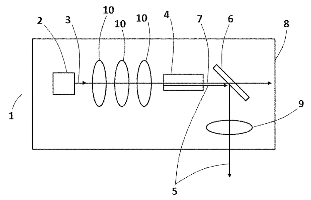
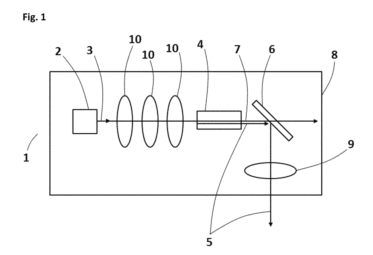
[0175]A third example of this invention is now disclosed. The third example is similar to the second example and common features may not be repeated. In this third example, which is illustrated in FIG. 20, the device 1 includes a light absorbing component 50 which partially or fully absorbs light with the wavelength of the source light 3 emitted by the laser light source 2. The light absorbing component 50 is attached to the nonlinear optical component 4, or alternatively it may be attached to the housing 8 close to, or otherwise in thermal contact with, the nonlinear optical component.

[0176]The light absorbing component 50 may be a coating of a light absorbing material applied to the nonlinear optical component or housing, such as for example a metal oxide layer applied by anodising or painting. The component may be a separate piece which is attached to the nonlinear optical component 4 or housing 8, for example by using a sc...

example 4

to Reduce Change in Beam Direction and / or Position

[0179]A fourth example of this invention is now disclosed. The fourth example is similar to the first example and common features may not be repeated. In this fourth example, which is illustrated in FIG. 21, the device 1 includes one or more optical components 60 which reduce the variation in direction or position of the output light beam 5 when operating conditions are changed. As described above, a variation in the operating conditions of a device according to any of the other examples in this disclosure may result in a change in the direction of the frequency-converted output light (e.g. second harmonic light) propagating out of the nonlinear optical component 4, for example if any change in operating condition causes a change in the wavelength of the source light 3 emitted by the laser light source 2. Experimental data showing this effect is displayed in FIG. 13. This data shows that the position of the frequency-converted output...

example 5

h Wavelength Stabilising Component

[0184]A fifth example of this invention is now disclosed. The fifth example is similar to the second example and common features may not be repeated. In this fifth example, which is illustrated in FIG. 22, the laser device 1 includes a wavelength stabilising component 70. The wavelength stabilising component 70 is configured to reduce a variation in the wavelength of the source light 3 emitted from the laser light source 2 when operating conditions are changed.

[0185]In this example the wavelength stabilising component is a surface diffraction grating, preferably a holographic diffraction grating, with a surface including an aluminium layer and with 3600 lines per mm. However, similar performance may be obtained using a grating with a different number of lines per mm, a grating with a different surface material layers (e.g. silver) or a different grating type (e.g. a ruled diffraction grating or volume Bragg grating). Furthermore, similar performance...


PUM


Abstract

A laser device includes a light source that emits a source light having a first peak wavelength. A nonlinear optical component performs a frequency conversion process that converts the source light into output light having a second peak wavelength. A stabilization component minimizes a mismatch error constituting a difference between the first peak wavelength and a wavelength for which the frequency conversion process in the nonlinear optical component has a maximum value. The stabilization component may include a housing that is thermally conductive between the light source and the nonlinear optical component to minimize a temperature difference between the light source and the nonlinear optical component. The laser device may include a focusing optical component that focuses the source light to have a convergence half angle that is larger than a convergence half angle that gives maximum output power, thereby increasing an acceptable range of the mismatch error.

Description

TECHNICAL FIELD[0001]This invention relates to a light source device using frequency-conversion of light from a laser light source for exemplary use to provide a deep ultraviolet light source device which has a wide operable range with respect to changes in operating conditions.BACKGROUND ART[0002]There are many examples of conventional photonic devices which exploit nonlinear optical properties of materials to convert light of a first frequency to light of a second frequency. Common examples exploit the nonlinear optical properties to provide second harmonic generation (SHG) whereby light with a first frequency emitted by a laser source (a “pump” laser) is converted to light with a second frequency which is double the first frequency. This process is commonly referred to as frequency-doubling. The frequency-doubled light is laser-like, meaning it has many features similar to the characteristics of light emitted by lasers such as narrow range of wavelengths, high beam quality and st...

Claims


Application Information

Patent Timeline
Patent Type & Authority Patents(United States)
IPC IPC(8): H01S3/109H01S3/04H01S3/08H01S3/137H01S3/0941H01S5/0239
CPCH01S3/109H01S3/0405H01S3/137H01S3/0941H01S3/08009H01S5/0071H01S5/0092H01S5/02438H01S5/02453H01S5/141G02F1/353H01S5/06837H01S5/0687H01S5/0239
Inventor WELNA, KARL PETERBOARDMAN, EDWARD ANDREWSMEETON, TIM MICHAELBERRYMAN-BOUSQUET, VALERIE
Owner SHARP FUKUYAMA LASER CO LTD
Why Eureka
Try Eureka