Method for signal detection in a gas analysis system

a gas analysis and signal detection technology, applied in the direction of interferometric spectrometry, optical radiation measurement, instruments, etc., can solve the problems of difficult detection of short changes in the concentration of gas to be analysed, reliable calibration, etc., and achieve the effect of short time constan

Active Publication Date: 2018-01-09
DRAGERWERK AG
View PDF6 Cites 0 Cited by
  • Summary
  • Abstract
  • Description
  • Claims
  • Application Information

AI Technical Summary

Benefits of technology

[0006]Hence, in view of the deficiencies of the state of the art, an object of the present invention is to provide a gas analysis system and to provide a method to operate the gas analysis system with a thermal sensor such that a reliable gas concentration determination is possible in spite of the long time constant of the sensor, so that the system is consistently sensitive to the gas species that is to be analyzed with certainty.
[0020]In a preferred embodiment of the method, the distance between the first and the second mirror of the Fabry-Perot interferometer depends on a voltage applied to the device for adjusting the distance, the voltage for continuously increasing or decreasing the distance being either continuously increased or continuously decreased. In such an embodiment, a control device of the gas analysis system can control the Fabry-Perot interferometer and the wavelength or the wavelength interval, in which the detector is sensitive, in a simple manner.
[0021]In another preferred embodiment, the radiation source is configured such that the intensity thereof is varied at a constant frequency, this variation being used to generate the time signal pulses. Such a configuration makes possible a detection of the time signal pulses together with the measured signal, preferably with the thermal sensor. As a result, the equipment cost is low.
[0026]This configuration makes it possible to use two radiation sources for the wavelength range, which is especially relevant in the case of breathing gas measurement, wherein the one radiation source can be operated with chronologically constant intensity and covers the long-wave range above 6 μm. The second radiation source, which is then preferably configured as an LED, can be used for the short-wave range between 2 μm and 6 μm. This LED can be modulated in its intensity at a constant frequency in a simple manner in order to generate the time signal pulses.
[0027]It is especially preferred to provide the LED with a collimation optics, so that a large part of the radiation generated by the diode can be focused not only in the gas measuring section, but also on the Fabry-Perot interferometer, so that the system can in turn operate efficiently.
[0032]Further, the second sensor may especially be a semiconductor detector, which is sensitive in the infrared range and especially in the wavelength range up to 6.0 μm. A semiconductor detector has the advantage that it has a very short time constant, so that it is unproblematic to detect the time signal pulses, which are generated by modulation of the intensity of one of the radiation sources, with this detector as well.

Problems solved by technology

In gas analysis systems of this type, however, the technical problem arises of achieving a reliable calibration of the sensor and of the measured values resulting from the sensor signal in relation to the wavelength and especially if thermal sensors are used which have long time constants.
However, this in turn would lead to brief changes in the concentration of the gas to be analyzed being able to be detected with difficulty only.

Method used


Image

  • Method for signal detection in a gas analysis system
  • Method for signal detection in a gas analysis system
  • Method for signal detection in a gas analysis system

Examples


Embodiment Construction

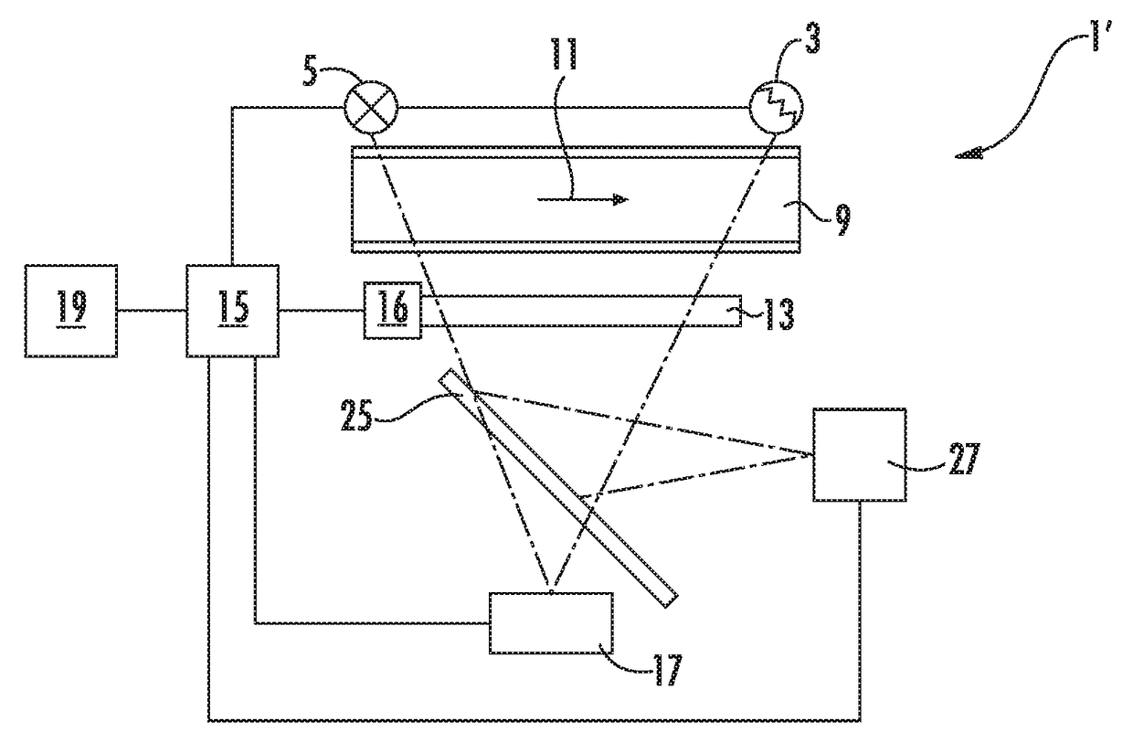
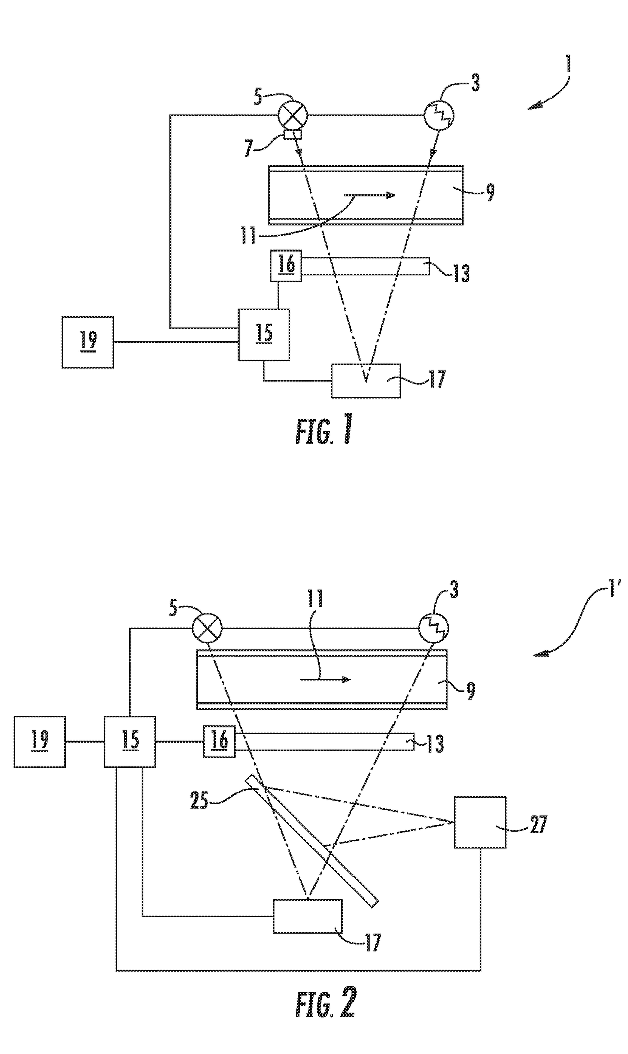
[0050]Referring to the drawings, a first preferred exemplary embodiment of a gas analysis system for carrying out the method according to the present invention shown in FIG. 1 has a first thermal radiation source 3 as well as a second radiation source 5, configured as an LED. In this exemplary embodiment the first radiation source 3 emits radiation in a first wavelength range Δλ1 between 3.5 μm and 12 μm. The second radiation source 5, which has its characteristic emission spectrum in a second wavelength range Δλ2 of 2 μm to 6 μm, is, in addition, equipped with a collimation optics 7 in this preferred exemplary embodiment, so that the radiation emitted by the second radiation source 5 is radiated out in only one direction. It is, however, radiation sources with other emission wavelengths may also be used.

[0051]The gas analysis system 1 has a gas measuring section in the form of a measuring cuvette 9, through which the gas to be measured and to be analyzed can flow along a flow direc...


PUM

PropertyMeasurementUnit
wavelength rangeaaaaaaaaaa

Abstract

A method for signal detection with a gas analysis system (1, 1′) includes a radiation source (3); a gas measuring section (9) containing gas to be measured; a Fabry-Perot interferometer (13); a thermal sensor (17) configured to cause a change in voltage between electrodes with electromagnetic radiation falling thereon and arranged such that radiation released by a second interferometer mirror falls on the thermal sensor. The method includes irradiating the gas measuring section with radiation source radiation, continuously increasing or decreasing a distance of interferometer mirrors during a generating of time signal pulses at a constant period of time from one another. After a predefined number of time signal pulses, the voltage generated between the electrodes is detected and stored as a measured signal value. After a further predefined number of time signal pulses, the voltage generated between the electrodes is detected again and stored as a measured signal value.

Description

CROSS REFERENCE TO RELATED APPLICATIONS[0001]This application claims the benefit of priority under 35 U.S.C. §119 of German Application 10 2015 012 429.3 filed Sep. 25, 2015, the entire contents of which are incorporated herein by reference.FIELD OF THE INVENTION[0002]The present invention pertains to a method for signal detection in a gas analysis system for the analysis of a gas to be measured with a radiation source which emits electromagnetic radiation in a first wavelength range; with a gas measuring section, in which the gas to be measured is contained, the gas measuring section being arranged in relation to the radiation source such that the radiation emitted by the radiation source passes through the gas measuring section; with a Fabry-Perot interferometer which has a first and a second semireflecting mirror that are arranged parallel to one another, and a device for changing the distance between the mirrors, the Fabry-Perot interferometer being arranged such that radiation ...

Claims


Application Information

Patent Timeline
Patent Type & Authority Patents(United States)
IPC IPC(8): G01N21/3504G01J3/10G01J3/45G01J3/26G01J3/42G01J3/36
CPCG01N21/3504G01J3/108G01J3/45G01J3/36G01J3/42G01J3/26
Inventor DREYER, PETERFORNASIERO, LIVIOTROLLSCH, ARNEJAHNS, ROBERT
Owner DRAGERWERK AG
Why Eureka
Try Eureka