
Method for manufacturing magnetoresistive element

a technology of magnetoresistive elements and manufacturing methods, which is applied in the selection of device materials, thermoelectric devices, and galvano-magnetic materials, etc., can solve the problems of deterioration of reliability or characteristics of elements, affecting the quality of materials, so as to reduce the sublimation of metal and improve the throughput

Active Publication Date: 2018-01-09
CANON ANELVA CORP
View PDF25 Cites 5 Cited by
  • Summary
  • Abstract
  • Description
  • Claims
  • Application Information

AI Technical Summary

Benefits of technology

The invention provides a way to make a magnetoresistive element that reduces the sublimation of metal during the oxidation process, while also improving the formation of a tunnel barrier layer of a metal oxide. This means that the amount of metal lost during the process is minimized, and the manufacturing process is made more efficient.

Problems solved by technology

Also, for example, when a metal film as a structural element of the MRAM is oxidized to form a barrier layer, the absence of quick oxidation of the metal film leads to mixing of impurities and in turn to deterioration in reliability or characteristics of the element.
However, in a case where a material for the metal film for use in the formation of the barrier layer is magnesium (Mg), when Mg is heated to the target temperature, Mg sublimes with increasing temperature, because Mg in particular is a sublimation-prone material.
Meanwhile, Mg may conceivably be formed in advance in a greater thickness than the designed value, allowing for the sublimation during deposition of Mg; however, this involves excessive deposition of Mg with respect to the designed value, thus leading to an increase in cost.

Method used


Image

  • Method for manufacturing magnetoresistive element
  • Method for manufacturing magnetoresistive element
  • Method for manufacturing magnetoresistive element

Examples


first embodiment

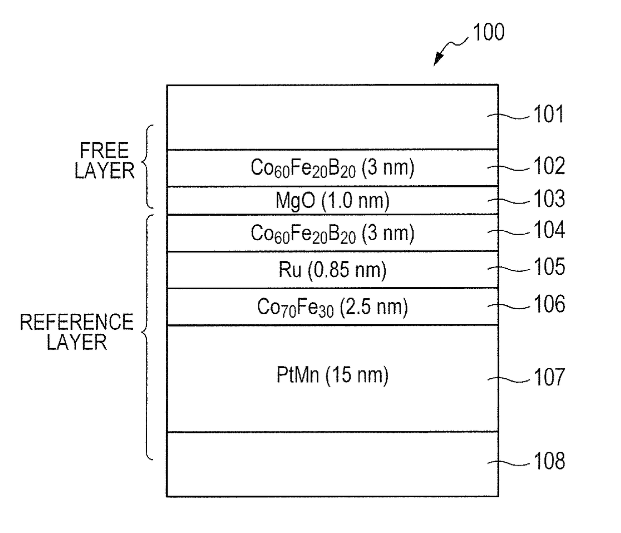
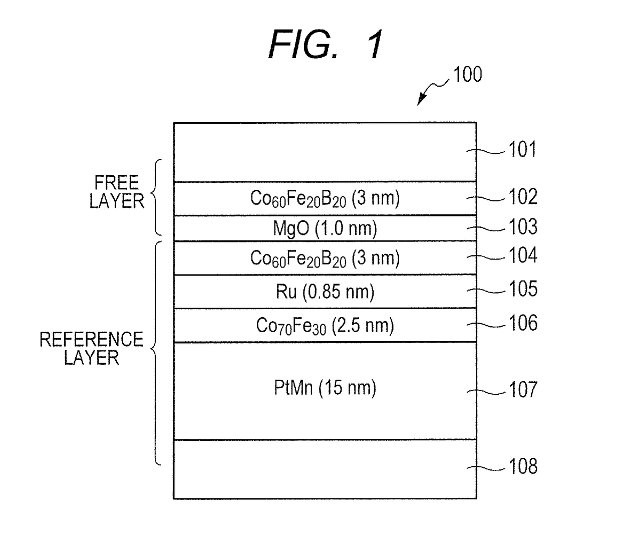
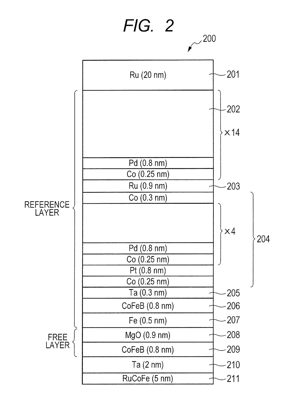
[0043]FIG. 4 is a schematic diagram illustrating a configuration of an oxidation process apparatus 400 according to the embodiment, under a substrate transport condition and under a first oxidation process (or a first oxidation process condition). FIG. 5 is a schematic diagram illustrating the configuration of the oxidation process apparatus 400 according to the embodiment, and illustrates another example of the first oxidation process. FIG. 6 is a schematic diagram illustrating the configuration of the oxidation process apparatus 400 according to the embodiment, under a second oxidation process (or a second oxidation process condition). In the embodiment, the oxidation process apparatus 400 forms a barrier layer of each element illustrated by way of example in FIGS. 1 to 3. In the embodiment, the barrier layer is made of MgO, and a substrate having Mg formed thereon is subjected to the oxidation process in the oxidation process apparatus 400 thereby to form MgO.

[0044]In the embodim...

second embodiment

[0080]In the first embodiment, the oxidation process space 410 smaller than the processing container 401 is formed in the processing container 401; however, the oxidation process space 410 may not be formed. FIG. 11 is a schematic diagram illustrating a general configuration of an oxidation process apparatus according to a second embodiment. An oxidation process apparatus 1100 has the same structure as that of the oxidation process apparatus 400 illustrated in FIGS. 4 to 6, except that the oxidation process apparatus 1100 does not include the cylindrical member 405.

[0081]FIG. 12 is a flowchart illustrating a procedure for an oxidation process in a step of forming a tunnel barrier layer according to the second embodiment.

[0082]At step S121, the slit valve of the substrate transport port 407 is opened to transport the substrate 403 having Mg formed thereon into the processing container 401, and the substrate 403 is mounted on the protrusion portion 404c in a protruding state. After co...


PUM


Abstract

Provided is a method for manufacturing a magnetoresistive element, including a step of forming a tunnel barrier layer, wherein the step of forming the tunnel barrier layer includes a deposition step of depositing a metal film on top of a substrate, and an oxidation step of subjecting the metal film to an oxidation process. The oxidation step includes holding the substrate having Mg formed thereon, on a substrate holder in a processing container in which the oxidation process is performed, supplying an oxygen gas to the substrate by introducing the oxygen gas into the processing container, at a temperature at which Mg does not sublime, and heating the substrate after the introduction of the oxygen gas.

Description

CROSS-REFERENCES TO RELATED APPLICATIONS[0001]This application is a continuation application of International Application No. PCT / JP2013 / 005249, filed Sep. 4, 2013, which claims the benefit of Japanese Patent Application No. 2012-278264 filed Dec. 20, 2012. The contents of the aforementioned applications are incorporated herein by reference in their entireties.TECHNICAL FIELD[0002]The present invention relates to a method for manufacturing a magnetoresistive element.BACKGROUND ART[0003]Heretofore, a magnetoresistive change element has been used mainly as an element for reading in a magnetic field from media of a hard disk drive. The magnetoresistive element utilizes a magnetoresistive effect of changing electrical resistance by application of a magnetic field to the element, and hard disk drive industry uses a TMR head using a tunnel magnetoresistive (TMR) effect of exhibiting a greater rate of resistance change than that of a GMR head using a giant magnetoresistive (GMR) effect, wh...

Claims


Application Information

Patent Timeline
Patent Type & Authority Patents(United States)
IPC IPC(8): H01L21/00H01L43/08H01L43/10H01L43/12H01L21/28H01L37/00H01L21/02H01L41/20H10N50/01H10N15/00H10N35/85H10N50/10H10N50/80
CPCH01L43/12H01L43/08H01L43/10H01L21/0226H01L21/02104H01L41/20H01L21/02263H01L21/02271H01L21/02436H01L21/28061H01L37/00H01L21/02205H10N50/10H10N50/01H10N50/85H10N15/00H10N35/85
Inventor SEINO, TAKUYANISHIMURA, KAZUMASAOKUYAMA, HIROKIOTANI, YUICHIMUROOKA, YUTASHIMANE, YOSHIMITSU
Owner CANON ANELVA CORP
Learn More