
Organic electroluminescence element

a technology of electroluminescent elements and organic materials, which is applied in the direction of organic semiconductor devices, electrical devices, semiconductor devices, etc., can solve the problems of uneven surface appearance, poor gas barrier property of transparent plastics compared to glass substrates, and uneven function of electronic devices, so as to improve light-emission efficiency, high-temperature storage stability, and maintain flexible aptitud

Active Publication Date: 2018-01-16
KONICA MINOLTA INC
View PDF15 Cites 4 Cited by
  • Summary
  • Abstract
  • Description
  • Claims
  • Application Information

AI Technical Summary

Benefits of technology

[0035]By the above-described means of the present invention, it can provide an organic electroluminescent element achieving a high-temperature storage stability and improved light-emission efficiency while maintaining flexible aptitude.
[0036]A formation mechanism or an action mechanism of the effects of the present invention is not clarified. However, it is supposed as follows.
[0037]Since a light-emission efficiency of an organic EL element will be decreased due to confinement or deactivation of the emitted light in the inside of the element, it is an effective embodiment to place a light extracting structure between the substrate and the electrode. However, such light extracting structure utilizes particles enabling to produce Mie scattering or geometrical scattering, or unevenness of 3 dimensions. These structures are required to be placed between the substrate and the electrode. As a method for forming these structures, various types of methods such as a coating process and a nanoimprint method have been proposed. Many effective methods have been proposed for the glass substrate in the past.
[0038]On the other hand, when the above-described light extracting structure is intended to form on a flexible substrate (for example, a film substrate), a high-temperature treatment cannot be done during the formation of the above-described structure due to the small heat resistance of the film substrate. That is the most disadvantage of the film substrate. As a result, a small amount of gas is emitted from the material composing these light extracting structures. An organic EL element is very sensitive to water or the gases emitted from various materials. When an organic EL element is exposed to these, degradation of the initial property of the production will be accelerated. As a result, light-emission efficiency and a lifetime of an organic EL element will be lowered.
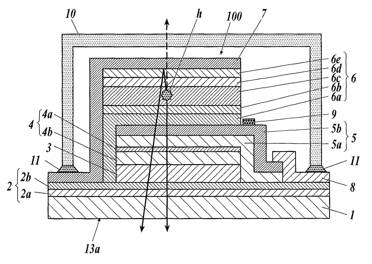
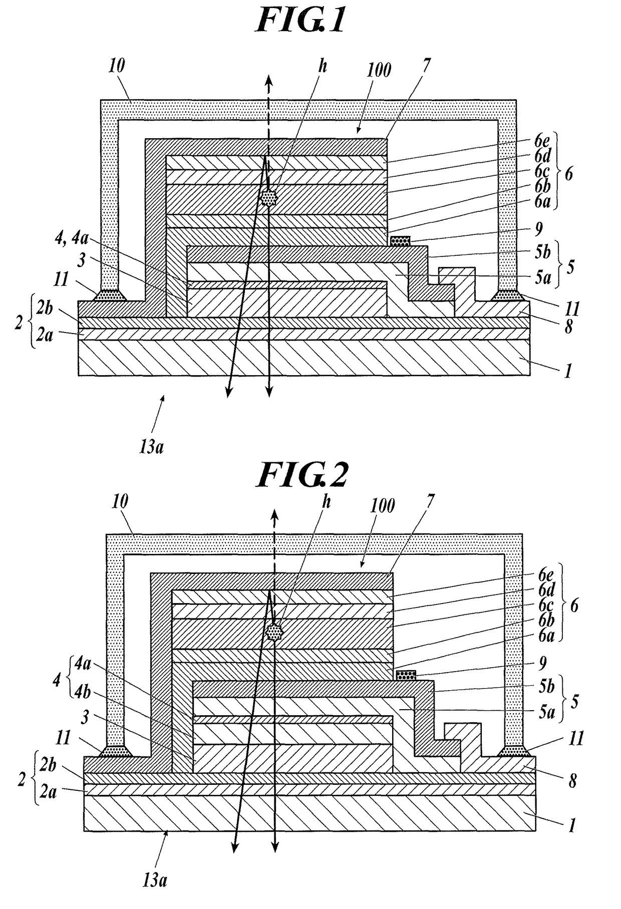
[0039]An organic EL element of the present invention has a highly effective light extracting structure capable of being formed on a film, and it has a smooth layer made of an oxide or a nitride of silicon or niobium on the light extracting structure. By this specific composition, a predetermined gas barrier property can be obtained without hindering the light extracting efficiency and the flexibility. Consequently, it is supposed that the high-temperature storage stability of a light-emitting element formed on a film substrate is increased and light-emission efficiency is also improved.

Problems solved by technology

However, a film substrate such as a transparent plastic has a problem of inferior gas barrier property compared with a glass substrate.
It has been known that the function of the electronic device will be deteriorated by the penetrated water vapor and oxygen gas when a substrate of inferior gas barrier property is used.
When a gas barrier layer or a light scatter layer is formed on a film substrate, it will be produced unevenness on the surface.
As a result, when a light-emitting unit having organic functional layers is formed thereon, it may be occurred deterioration of keeping property or short-circuit (electric short) under the environment of high-temperature and high-humidity.
However, it has not been disclosed technology to achieve both gas barrier property and bend (curvature) repeating resistance, namely, flexible aptitude.

Method used


Image

  • Organic electroluminescence element
  • Organic electroluminescence element
  • Organic electroluminescence element

Examples


examples

[0455]Hereafter, the present invention will be described specifically by referring to examples, however, the present invention is not limited to them. In examples, the term “%” is used. Unless particularly mentioned, it represents “mass %”.

>

(1) Preparation of Substrate 1

(1-1) Film Substrate

[0456]A biaxially oriented polyethylene naphthalate film (PEN film having a thickness of 100 μm and a width of 350 mm, Neotex™ Q65FA made by Teijin DuPont Films Co. Ltd.) was used as a film substrate.

(1-2) Preparation of Primer Layer

[0457]In the subsequent step, an UV-curable organic / inorganic hybrid hard coat material OPSTAR Z7501 was applied with a wire bar to an easy-adhesion surface of the film substrate to obtain a coated layer with a dry thickness of 4 μm. Then, the layer was dried at 80° C. for three minutes, and was cured with a high pressure mercury lamp at 1.0 J / cm2 under an air atmosphere to form a primer layer.

[0458]The maximum cross-section height Ra (p) that indicates the surface rou...


PUM


Abstract

Provided is an organic electroluminescent element including a film substrate having thereon: at least one gas barrier layer, a light scatter layer, at least one smooth layer, and a light-emitting unit containing an organic functional layer interposed between a pair of electrodes, laminated in this order, wherein the light scatter layer contains a binder and light scatter particles having an average particle size of 0.2 μm or more to less than 1 μm; and the smooth layer contains an oxide or a nitride of silicone or niobium as a main component.

Description

CROSS REFERENCE TO RELATED APPLICATIONS[0001]This is the U.S. national stage of application No. PCT / JP2014 / 081725, filed on Dec. 1, 2014. Priority under 35 U.S.C. § 119(a) and 35 U.S.C. § 365(b) is claimed from Japanese Application No. 2013-252693, filed Dec. 6, 2013, the disclosure of which is also incorporated herein by reference.TECHNICAL FIELD[0002]The present invention relates to an organic electroluminescent element achieving a high-temperature storage stability and improved light-emission efficiency while maintaining flexible aptitude.BACKGROUND[0003]In recent years, in the field of electronic devices, there have been added requirements of long-term reliability, flexible shape, and enabling curved display in addition to light weight and large size. The used of a film substrate such as a transparent plastic has been started in place of a glass substrate having a heavy weight and difficult in making a large size.[0004]However, a film substrate such as a transparent plastic has ...

Claims


Application Information

Patent Timeline
Patent Type & Authority Patents(United States)
IPC IPC(8): H01L51/52H01L51/56
CPCH01L51/5268H01L51/5215H01L51/5253H01L51/56H01L51/5203H01L2251/5369H01L51/5212H01L2251/301H01L2251/303H01L2251/5338H01L51/524H10K50/805H10K50/814H10K50/816H10K50/841H10K50/854H10K50/844H10K2102/00H10K2102/311H10K2102/331H10K50/858H10K71/00
Inventor KUROKI, TAKAAKITAKEDA, AKIHIKOKOBAYASHI, YASUNOBU
Owner KONICA MINOLTA INC
Learn More