
System for chemically absorbing carbon dioxide in combustion exhaust gas

a carbon dioxide and combustion exhaust technology, applied in the field of systems for chemically absorbing carbon dioxide (co2), can solve the problems of unnecessarily heated reflux water, heated, etc., and achieve the effects of reducing the amount of water vapor fed, reducing the amount of heat used to heat reflux water, and reducing the amount of absorbing liquid vapor

Active Publication Date: 2018-02-27
MITSUBISHI POWER LTD
View PDF9 Cites 1 Cited by
  • Summary
  • Abstract
  • Description
  • Claims
  • Application Information

AI Technical Summary

Benefits of technology

[0040]The present invention can reduce the absorbing liquid vapor that should be fed from the reboiler 40 to the regeneration column 20; consequently, this can reduce the amount of water vapor fed from the plant vapor system to the reboiler. That is, upon reduction in the amount of reflux water added dropwise to the packed bed for CO2 desorption, the heat of the absorbing liquid vapor fed from the reboiler is only applied to the CO2-rich liquid; consequently, this can reduce the amount of heat used to heat the reflux water. Therefore, when the CO2 chemical absorption system of the present invention is installed, the energy loss in the entire power plant can be reduced.

Problems solved by technology

This is uneconomical in that the reflux water, which is not essentially necessary to be heated, is unnecessarily heated.

Method used


Image

  • System for chemically absorbing carbon dioxide in combustion exhaust gas
  • System for chemically absorbing carbon dioxide in combustion exhaust gas
  • System for chemically absorbing carbon dioxide in combustion exhaust gas

Examples


Embodiment Construction

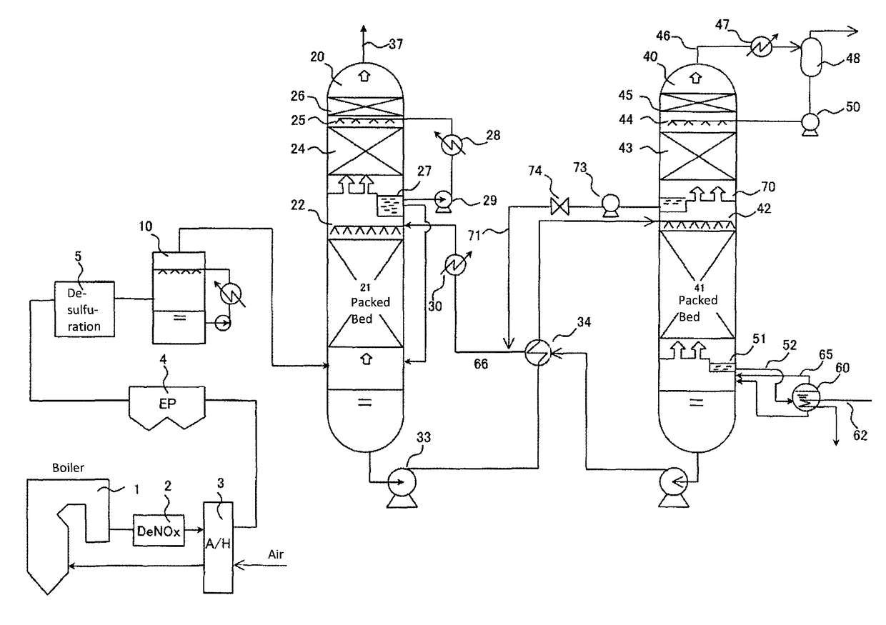
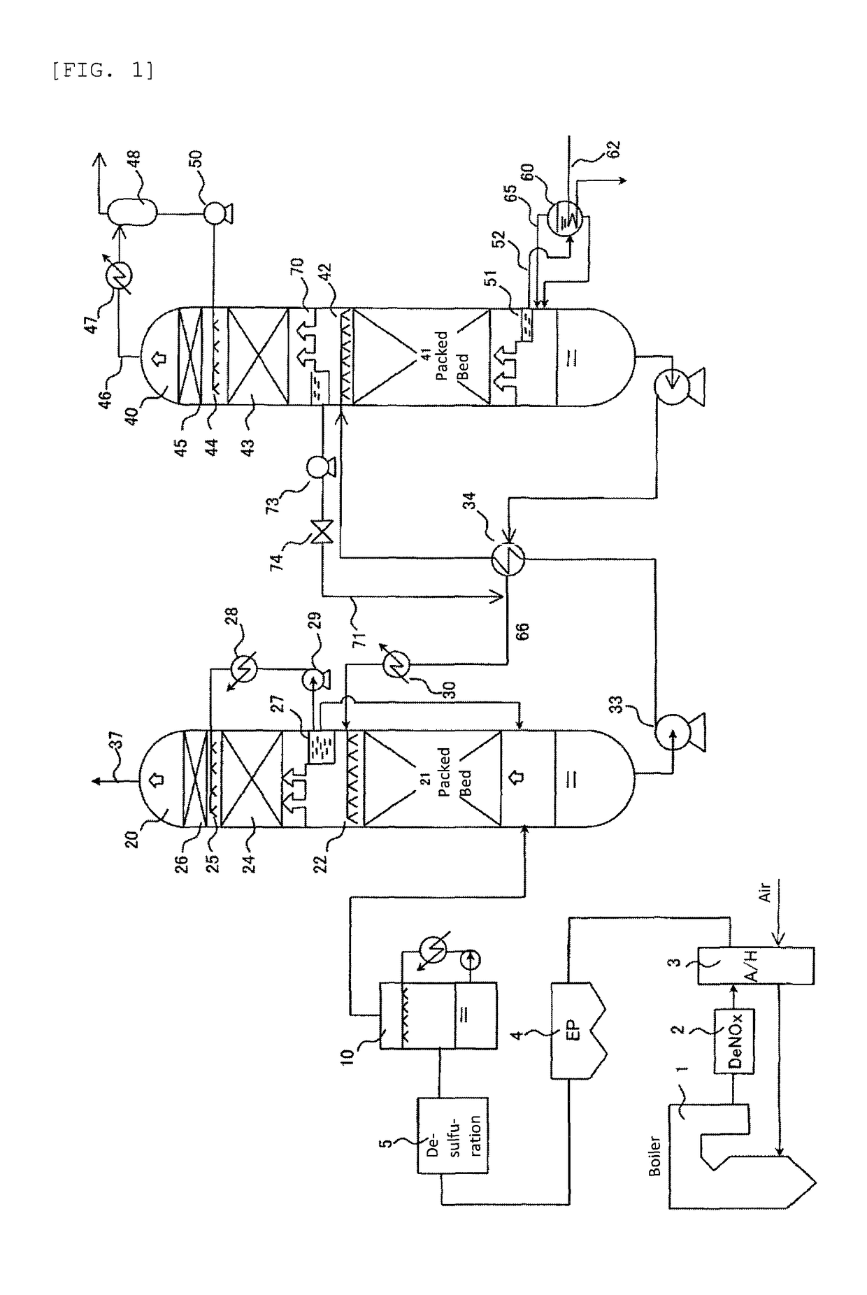
[0044]FIG. 1 shows one embodiment of the CO2 chemical absorption system according to the present invention. The difference from the conventional system shown in FIG. 3 is that a reflux water collection plate 70 is provided directly below the water washing part packed bed 43 in the regeneration column 40 so that the liquid collected by the reflux water collection plate 70 is returned to the pipe 66 from the regeneration column 40 toward the absorption column 20.

[0045]The absorbing liquid vapor fed from the reboiler 60 passes through an absorbing liquid collection plate 51, and is sent to the packed bed 41. In the packed bed 41, the absorbing liquid vapor and a CO2-rich liquid are brought into direct contact to desorb CO2 gas from the CO2-rich liquid. Water vapor entrained in the desorbed CO2 gas passes through the reflux water collection plate 70 and is fed to the water washing part 43, wherein the water vapor is cooled and amine mist is removed. The mist is further removed by the mi...


PUM

PropertyMeasurementUnit
temperatureaaaaaaaaaa
chemical absorptionaaaaaaaaaa
temperatureaaaaaaaaaa

Abstract

A carbon dioxide (CO2) chemical absorption system comprising: a CO2 absorption column for separating CO2 from combustion exhaust gas by absorbing the CO2 in the combustion exhaust gas with a CO2 absorbing liquid mainly composed of an aqueous alkanolamine solution; a regeneration column for regenerating the CO2 absorbing liquid by desorbing CO2 gas from the CO2 absorbing liquid that has absorbed CO2; a condenser for condensing water vapor entrained in the desorbed CO2 gas discharged from the top of the regeneration column, thereby obtaining reflux water; a pipe for returning all or part of the reflux water obtained by the condenser to the top of the regeneration column, and dispersing the reflux water in the regeneration column; a collection plate for collecting the reflux water dispersed in an upper portion of a packed bed in the regeneration column; a pipe for sending the regenerated CO2 absorbing liquid from the bottom of the regeneration column to the top of the absorption column; and a pipe for joining the reflux water collected by the collection plate into the pipe for sending the regenerated CO2 absorbing liquid.

Description

TECHNICAL FIELD[0001]The present invention relates to a system for chemically absorbing carbon dioxide (CO2) from combustion exhaust gas generated in combustion equipment, such as a boiler. More specifically, the present invention relates to the structure of a regeneration column of a CO2 chemical absorption system, and the system structure of peripheral devices of the regeneration column.BACKGROUND ART[0002]Thermal power generation facilities and boiler facilities generate a quantity of carbon dioxide as a result of burning a large amount of fuel, such as coal, heavy oil and the like. From the viewpoint of air pollution or global warming, many countries promote the regulation of large emissions of carbon dioxide (hereinafter abbreviated as “CO2”). As a technique for separating and recovering CO2, a chemical absorption method using an aqueous alkanolamine solution as a CO2 absorbing liquid is widely known. FIG. 3 shows one embodiment of a power generation plant comprising a conventi...

Claims


Application Information

Patent Timeline
Patent Type & Authority Patents(United States)
IPC IPC(8): B01D53/62B01D53/14
CPCB01D53/62B01D53/1425B01D53/1475Y02C10/06B01D2259/65Y02C10/04B01D2252/20478Y02A50/20Y02C20/40
Inventor HIGASHI, HIDEAKISHIMAMURA, JUNKOBAYASHI, KAZUKI
Owner MITSUBISHI POWER LTD
Learn More