TFT device for measuring contact resistance and measurement method for contact resistance

a technology of contact resistance and measurement method, which is applied in the direction of resistance/reactance/impedence, individual semiconductor device testing, instruments, etc., can solve the problems of obtaining a conduction current having a greater current under a lower vds, and achieve the effect of increasing measurement accuracy, saving distribution region, and increasing utilization of experimental region

Active Publication Date: 2018-02-27
TCL CHINA STAR OPTOELECTRONICS TECH CO LTD
View PDF3 Cites 1 Cited by
  • Summary
  • Abstract
  • Description
  • Claims
  • Application Information

AI Technical Summary

Benefits of technology

[0009]The present invention provides a TFT device for measuring a contact resistance and measurement method for a contact resistance, which can solve a poor uniformity and inaccurate measurement result problem because of using multiple TFT devices for measuring in the conventional art.
[0024]The beneficial effects of the present invention are: comparing with the conventional art, through disposing at least three doping regions on the active layer of the TFT, when measuring a contact resistance, selecting two of the at least three doping regions as test points to form a testing group to perform measuring, and through selecting different testing groups to change the channel length so that multiple total resistances under different channel lengths can be measured, and obtaining multiple measurement data on one TFT device can be realized such that manufacturing multiple TFT devices is not required. The present invention maximally integrates devices having different channel lengths at a same location in one TFT so that the uniformity is well, the manufacturing process, the film forming quality and the interface property are similar in a maximum degree. Accordingly, a measurement accuracy is increased, saving the distribution region at the same time, increasing the utilization of the experimental region.

Problems solved by technology

In the research of the TFT device, how to obtain a conduction current having a greater current under a lower Vds is always a key problem.

Method used


Image

  • TFT device for measuring contact resistance and measurement method for contact resistance
  • TFT device for measuring contact resistance and measurement method for contact resistance
  • TFT device for measuring contact resistance and measurement method for contact resistance

Examples


Embodiment Construction

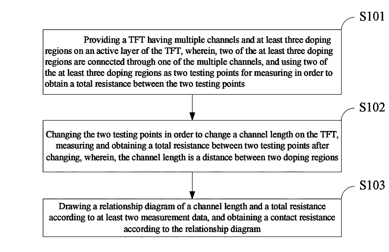
[0030]The following content combines figures and embodiments for detail description of the present invention.

[0031]With reference to FIG. 3 and FIG. 4, FIG. 3 is a top view of a TFT device for measuring a contact resistance according to an embodiment of the present invention; and FIG. 4 is a schematic lamellar structure diagram of a cross section of a TFT device for measuring a contact resistance according to an embodiment of the present invention.

[0032]The present invention provides a TFT for measuring a contact resistance. The TFT includes an active layer, a gate electrode 300 and a gate insulation layer 500.

[0033]Wherein, the active layer is provided with a channel 100 and at least three doping regions 200. Two doping regions 200 are connected through the channel 100. When measuring a contact resistance, using two of the at least three doping regions 200 as testing points.

[0034]The gate electrode 300 is disposed correspondingly to the channel 100.

[0035]The gate insulation layer 5...


PUM


Abstract

TFT device for measuring a contact resistance and measurement method for a contact resistance are disclosed. The TFT includes an active layer, a gate electrode and a gate insulation layer. The active layer includes a channel and at least three doping regions, wherein, two of the at least three doping regions is connected through a channel, when measuring the contact resistance, using two of the at least three doping regions as testing points for measuring. The gate electrode disposed correspondingly to the channel. The gate insulation layer for insulating the active layer from the gate electrode. The uniformity of the present invention is well, the manufacturing process, the film forming quality and the interface property are similar in a maximum degree. Accordingly, a measurement accuracy is increased, saving the distribution region at the same time, increasing the utilization of the experimental region.

Description

BACKGROUND OF THE INVENTION[0001]1. Field of the Invention[0002]The present invention relates to a thin-film-transistor (TFT) technology field, and more particularly to a TFT device for measuring a contact resistance and measurement method for a contact resistance.[0003]2. Description of Related Art[0004]A Thin-Film-Transistor (TFT) is widely applied in a semiconductor industry, a display industry, a transducer industry and a chip industry. The research for the field effect transistor mainly includes stability and functionality.[0005]A TFT is a triode, which includes a gate electrode, a source electrode and a drain electrode. When a gate voltage is greater than a threshold voltage (Vth), an active layer generates a carrier gathering and an energy band bending under the function of the gate voltage in order to form a conductive channel. At this time, when a non-zero voltage is applied between the source electrode and the drain electrode, the carrier can move in a predetermined direct...

Claims


Application Information

Patent Timeline
Patent Type & Authority Patents(United States)
IPC IPC(8): G01R31/02H01L51/10G01R31/26H01L51/05H01L51/00
CPCG01R31/2607H01L51/0031H01L51/105H01L51/0558H01L51/0566H01L51/0545H10K71/70H10K10/488H10K10/484H10K10/466H10K10/84G01R27/02G01R31/26
Inventor SUN, BOZOU, XIAOLING
Owner TCL CHINA STAR OPTOELECTRONICS TECH CO LTD
Why Eureka
Try Eureka