Al technical title is built by PatSnap Al team. It summarizes the technical point description of the patent document.
a technology of housing and lens, applied in the field of housing lenses, can solve the problems of difficult manufacturing of contact lenses with internal fluidic structures such as chambers, easy wear and use, and poor optical performance of prior methods and apparatus for forming manufacturing lenses such as contact lenses, and achieve the effect of increasing optical power and optical power
Active Publication Date: 2018-03-06
ONEFOCUS VISION
View PDF59 Cites 13 Cited by
Summary
Abstract
Description
Claims
Application Information
AI Technical Summary
This helps you quickly interpret patents by identifying the three key elements:
Problems solved by technology
Method used
Benefits of technology
[0010]The lens comprises an internal cavity structure formed by dissolution of a soluble insert material. The internal soluble material may dissolve through a body of a lens such as a contact lens in order to form the cavity within the contact lens. The cavity within the lens can be shaped in many ways, and corresponds to the shape of the dissolved material, such that many internal cavity shapes can be readily fabricated within the contact lens. The insert can be placed in a mold with a pre-polymer material, and the pre-polymer material cured with the insert placed in the mold to form the lens body. The polymerized polymer may comprise a low expansion polymer in order to inhibit expansion of the lens when hydrated. The polymerized material can be hydrated and the insert dissolved in order to form the cavity with the desired shape within the lens body. The polymer may comprise a hydrogel when hydrated. The soft contact lens material comprises a sufficient amount of cross-linking to provide structure to the lens and shape the cavity, and allows water and solutes to diffuse in and out of the cavity in order to establish equilibrium of the cavity with the external environment of the lens body. The insert comprise a molecular weight sufficiently low to diffuse out of the lens body when hydrated, and sufficiently high to provide strength to the insert for handling and placement in the lens mold. The diffusion of the dissolved insert material away from the cavity may inhibit osmotic pressure and expansion of the cavity as the material dissolves, such that the structural integrity of the contact lens and cavity can be preserved. After dissolution of the insert, the shape of the cavity corresponds to the three dimensional shape profile of the insert material, such that the cavity can be shaped in many ways.
[0133]In many embodiments, the inner cavity providing optical correction may be encapsulated on an anterior side and a posterior side with the contact lens body within an optically used portion of the cavity. The anterior side of the contact lens body may deflect when the contact lens comprises a presbyopia correcting near vision configuration with inflation and may provide increased optical power of the inner portion of the cavity. The deflection may provide uniform changes in optical power of the inner portion of the cavity.
Problems solved by technology
The prior methods and apparatus for forming manufacturing lenses such as contact lenses can be less than ideal in at least some respects.
For example, contact lenses with internal fluidic structures such as chambers can be challenging to manufacture in at least some instances.
Neither approach is well accepted by wearers of contact lenses, and there is a continuing unmet need for an accommodating contact lens with a dynamically variable optic that has a single variable focal length, which is easily worn and used.
The manufacture of such a device can be more complicated than would be ideal.
The prior lenses may have less than ideal optical performance, and can be more difficult to use and manufacture than would be ideal.
In some instances, the prior contact lenses may provide less than ideal responses to eyelid pressure, and may not change shape in response to eyelid pressure as readily as would be ideal.
Although modules embedded in accommodating contact lenses can be effective, such modules can result in greater complexity and cost than would be ideal.
Also, embedded modules may provide non-ideal amounts of resistance to movement of the structures of an accommodating contact lens, depending upon the stiffness of the tensile modulus of the membrane comprising the module.
Method used
Image
Click on the blue label to locate the original text in one second.
Reading with bidirectional positioning of images and text.
Examples
Embodiment Construction
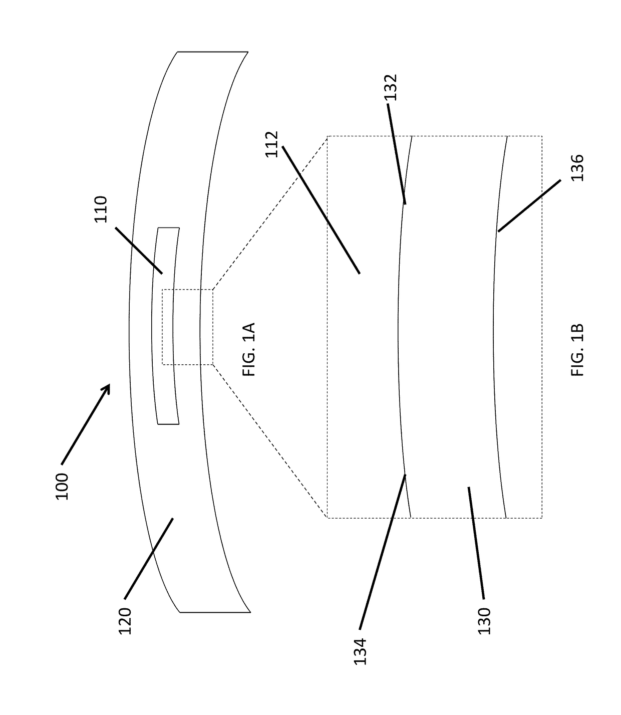
[0209]The cavity lenses disclosed herein are well suited for combination with many prior art lenses, such as contact lenses. The cavity lens can be combined with accommodating soft contact lenses or accommodating intraocular lenses, for example.
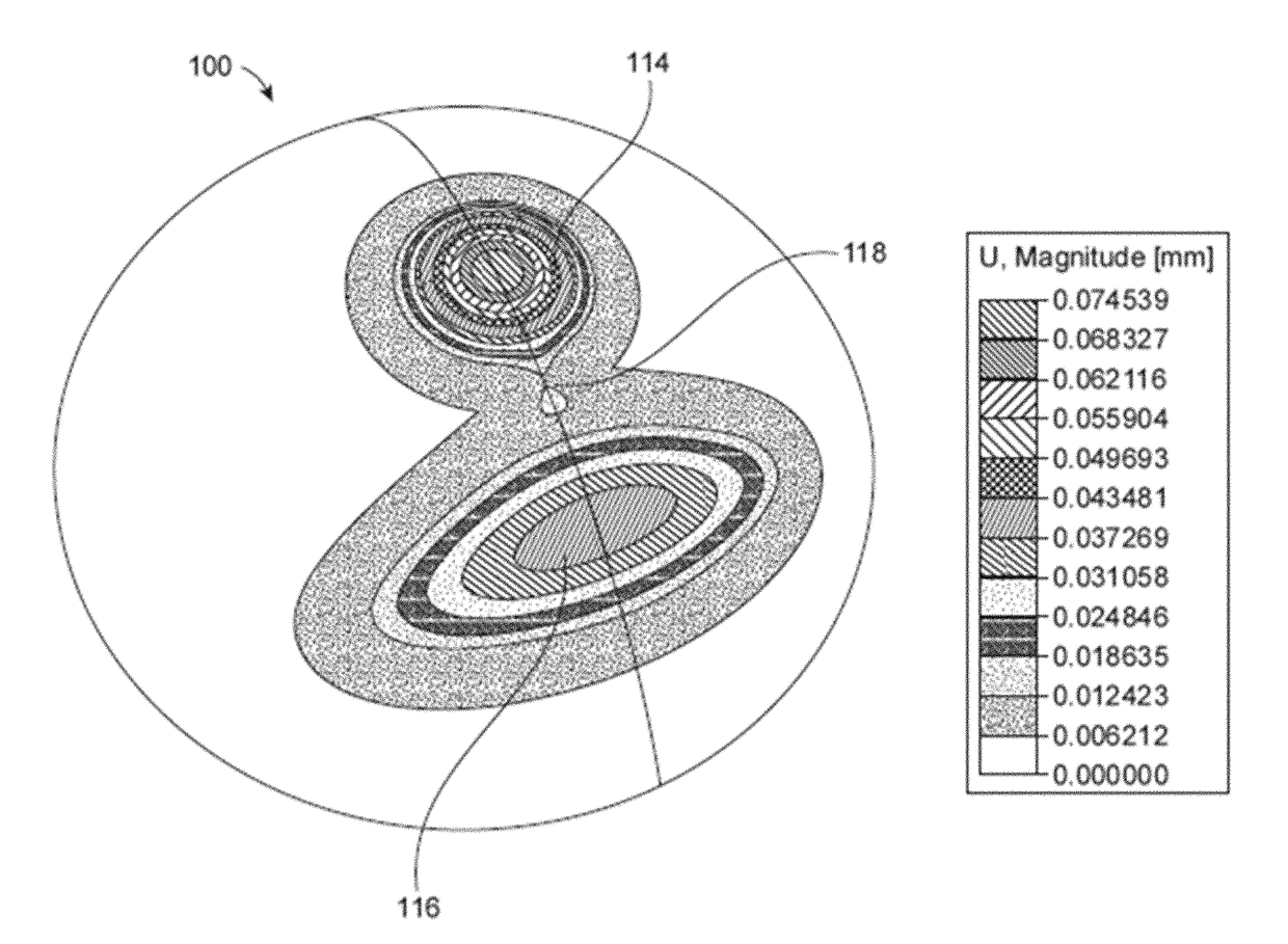
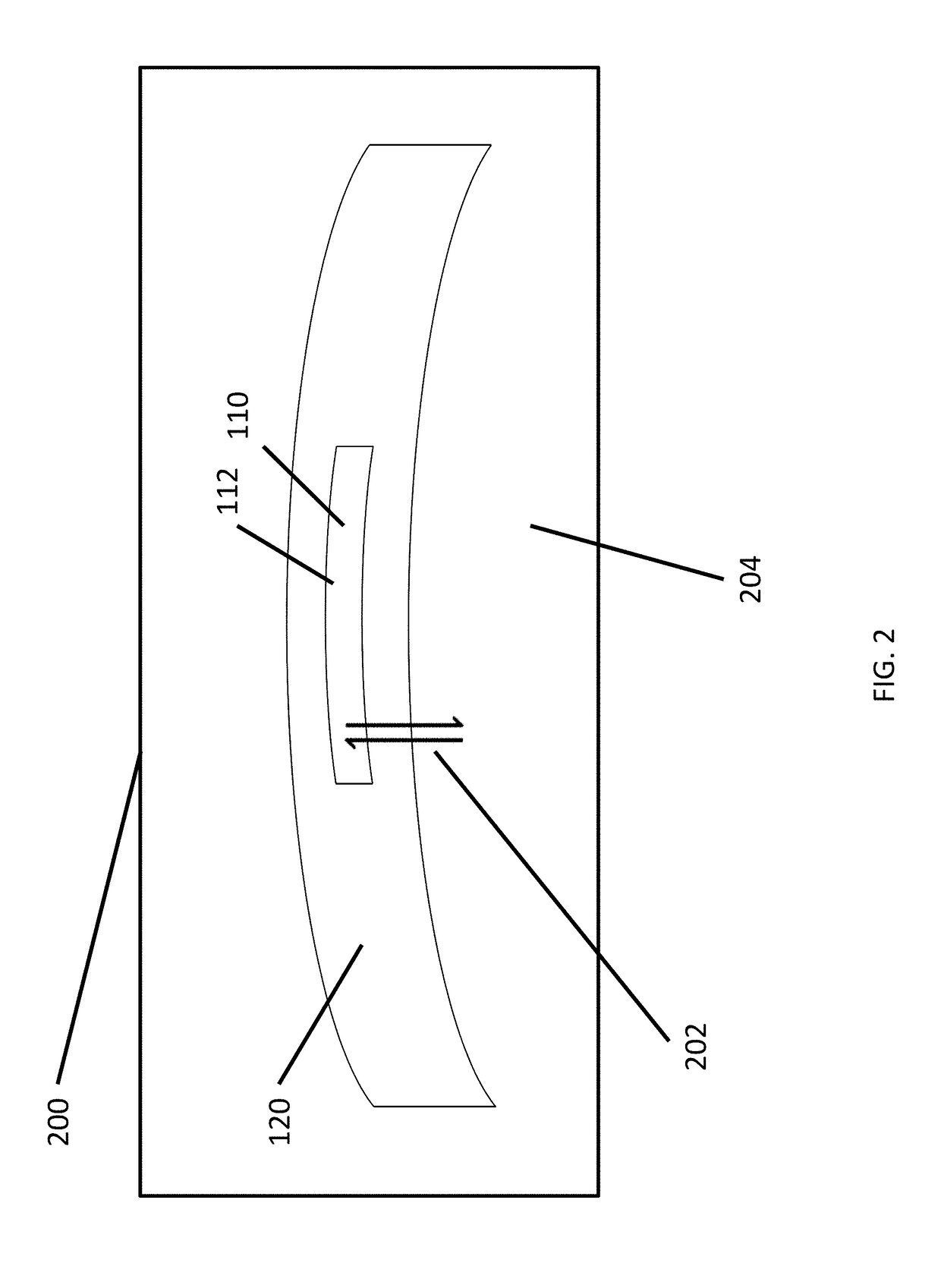
[0210]A soft contact lens comprising a cavity filled with a liquid functions as a dynamic accommodating contact lens that provides the required refractive correction to presbyopes at all distances from far to near. The cavity comprises an optical chamber aligned with the optical center of the lens itself, and a peripheral chamber positioned vertically below the optical chamber and connected to the optical chamber by means of a channel. When fitted on an eye, the optical chamber of the cavity is positioned over the center of the pupil while the peripheral chamber is positioned to interact with the lower eyelid at down-gaze. Pressure from the lower eyelid forces fluid from the peripheral chamber into the optical chamber, causing the cavity to i...
PUM
Abstract
A lens comprises an internal cavity structure formed by dissolution of a soluble insert material. The internal soluble material may dissolve through a body of a lens such as a contact lens in order to form the cavity within the contact lens. The cavity within the lens can be shaped in many ways, and corresponds to the shape of the dissolved material, such that many internal cavity shapes can be readily fabricated within the contact lens. The insert can be placed in a mold with a pre-polymer material, and the pre-polymer material cured with the insert placed in the mold to form the lens body. The polymerized polymer may comprise a low expansion polymer in order to inhibit expansion of the lens when hydrated. The polymer may comprise a hydrogel when hydrated. The soft contact lens material comprises a sufficient amount of cross-linking to provide structure to the lens and shape the cavity.
Description
CROSS-REFERENCE[0001]This application is a continuation application of PCT / US2016 / 061700, filed on 11 Nov. 2016, entitled “ACCOMMODATING LENS WITH CAVITY”, which is a non-provisional of, and claims the benefit of U.S. Prov. Ser. App. No. 62 / 327,938, filed on 26 Apr. 2016, entitled “ACCOMMODATING LENS WITH CAVITY”, and U.S. Prov. Ser. App. No. 62 / 254,093, filed on 11 Nov. 2015, entitled “ACCOMMODATING LENS WITH CAVITY”, the entire disclosures of which are incorporated herein by reference.[0002]The subject matter of the present application is related to the following patent applications: PCT / US2014 / 013427, filed on 28 Jan. 2014, entitled “Accommodating Soft Contact Lens”; PCT / US2014 / 013859, filed on Jan. 30, 2014, entitled “Manufacturing Process of an Accommodating Contact Lens”; PCT / US2014 / 071988, filed on Dec. 22, 2014, entitled “Fluidic Module For Accommodating Soft Contact Lens”; U.S. application Ser. No. 62 / 031,324, filed Jul. 31, 2014, entitled “Sacrificial Molding Process for a...
Claims
Application Information
Patent Timeline
Application Date:The date an application was filed.
Publication Date:The date a patent or application was officially published.
First Publication Date:The earliest publication date of a patent with the same application number.
Issue Date:Publication date of the patent grant document.
PCT Entry Date:The Entry date of PCT National Phase.
Estimated Expiry Date:The statutory expiry date of a patent right according to the Patent Law, and it is the longest term of protection that the patent right can achieve without the termination of the patent right due to other reasons(Term extension factor has been taken into account ).
Invalid Date:Actual expiry date is based on effective date or publication date of legal transaction data of invalid patent.