Single-side double-inclined-surface disc-type brake

a disc brake and double-inclination technology, applied in the direction of mechanically actuated brakes, actuators, brake types, etc., can solve the problems of low efficiency factor, large size, complicated structure, etc., and achieve high self-energizing capacity, efficiency factor, and better performance

Active Publication Date: 2018-03-20
CHENGDU SHUANGCHEN TECH CO LTD
View PDF9 Cites 0 Cited by
  • Summary
  • Abstract
  • Description
  • Claims
  • Application Information

AI Technical Summary

Benefits of technology

[0012]A single-side double-inclined-surface disc brake is provided which has the better performance of the common disc brake in the prior art without having the disadvantages of heat recession and water recession. As the brake has a high self-energizing capacity and the advantages of a drum-type brake, the energizing effect of the present invention can be much higher than that of the drum-type brake, and can be self-energized by one times—dozens of times (efficiency factor). It does not have the problems existing in the common disc brake, for example, the small braking force (low efficiency factor), an additional power booster (for a car) being required, difficult to arrange the parking braking thereon, the unstable security and the high cost. Furthermore, if the parking is arranged thereon, it does not increase the cost, thus saving much cost, particularly a diesel car, a new energy car (for example, an electric and dual-fuel car), which use the brake of the invention, can save more than 30% of cost than that of a brake system in the prior art. A power boosting system is not used on the car, an engine does not need to provide enough vacuum to the power boosting system, the idle rotation speed of the engine is only used to maintain its normal rotation, therefore, the idle rotation speed can be reduced greatly, much fuel and money can be saved particularly during traffic jams and at traffic lights, thus saving energy and reducing pollution. It does not use the power boosting system, thereby reducing the chance of a failure and greatly improving security. Particularly, it has very high self-energizing, is very easily controlled, and is easily taken as an electrically controlled disc brake system (EMB). It can hence save a lot of hydraulic mechanisms, mechanical mechanisms and electronic control mechanisms, and is directly controlled by CPU (a computer) of a car. Therefore, it has the advantages of a simple structure, a low cost and a fast braking response, thereby greatly improving the security of the brake system. This is exactly the difficult problem which the automotive circle eagerly want to but fail to resolve. It can also compensate for the deformation of a machine body (a clamp body) of the brake produced when the braking is carried out, to reduce an operation stroke and increase the energizing ratio of the brake. Therefore, a control force is reduced and a braking force is increased. As the brake can produce very much positive pressure, the requirement for a brake shoe can be lowered greatly, particularly as its friction factor (coefficient of friction) can be reduced from 0.4 to 0.05, its selection range can be expanded by many times, and a material of the brake shoe can hence be very easily selected. Therefore, the brake of the invention is a new generation of a brake which combines the advantages of the common disc brake and the drum-type brake and has better performance, security, cost, energy-saving and environment protection.

Problems solved by technology

However, such self-energizing disc brake needs inclined surfaces to be arranged at two sides of the brake disc, thereby causing the disadvantages of bigger size, complicated structure and too many sealing parts.
However, the disc brake has small braking force (low efficiency factor) and no self-energizing effect.
It requires power assistance (a vacuum booster for a gasoline car) to brake the car, and is difficult to arrange a parking brake and an emergency brake.
It is high cost, and the braking force will be very small after the engine is off, especially after the car has an accident flameout.
Since the disc brake uses the hydraulic drive, it has a security risk of being lag which may fail to meet the security requirement.
In this case, the car needs more fuel when the driver waits for traffic lights and during traffic jams, which is not good for the economy and the environment.
In addition, when the brake is used in a diesel car, a double energy car and an electrical car, it needs to be provided additionally with a vacuum pump, which would significantly increase the costs.
The common disc brake in the prior art also cost much when being provided as a parking brake.
So far the disclosed electrically controlled disc brake cannot be exactly controlled.
Another method used therein needs a high powered and big-sized motor which consumes lots of electricity that the power source can hardly supply.
Additionally, the big size of the motor makes itself hard to be mounted by the wheel.
Furthermore, the high cost of the high-powered and big-sized motor affects its implementation.
This disclosure also solves the problem that it is difficult to control the self-energizing effect of the disc brake in the prior art.
However, the motor of the disc brake which carries out electrical control (EMB) in the prior art has very high power, big size and huge electric energy consumption, thereby affecting its use and promotion.
It also solves the problems in the self-energizing disc brake in Patent Application No. 201110291009.9, in which both sides of the brake disc need an inclined surface, resulting in the complicated structure, the low stiffness of the jaw, too many parts to be sealed, and the troubles of sealings.

Method used


Image

  • Single-side double-inclined-surface disc-type brake
  • Single-side double-inclined-surface disc-type brake
  • Single-side double-inclined-surface disc-type brake

Examples


Embodiment Construction

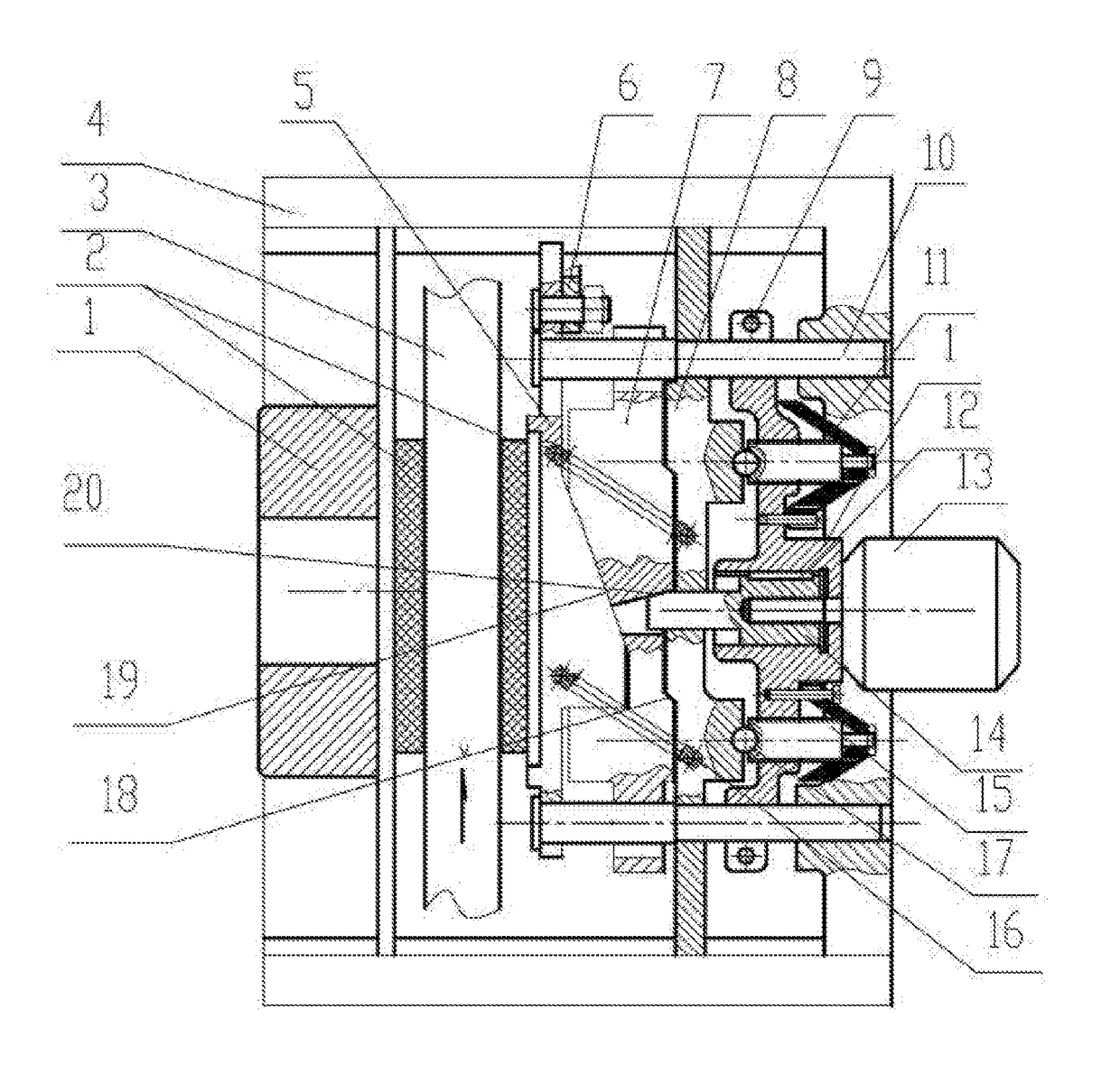
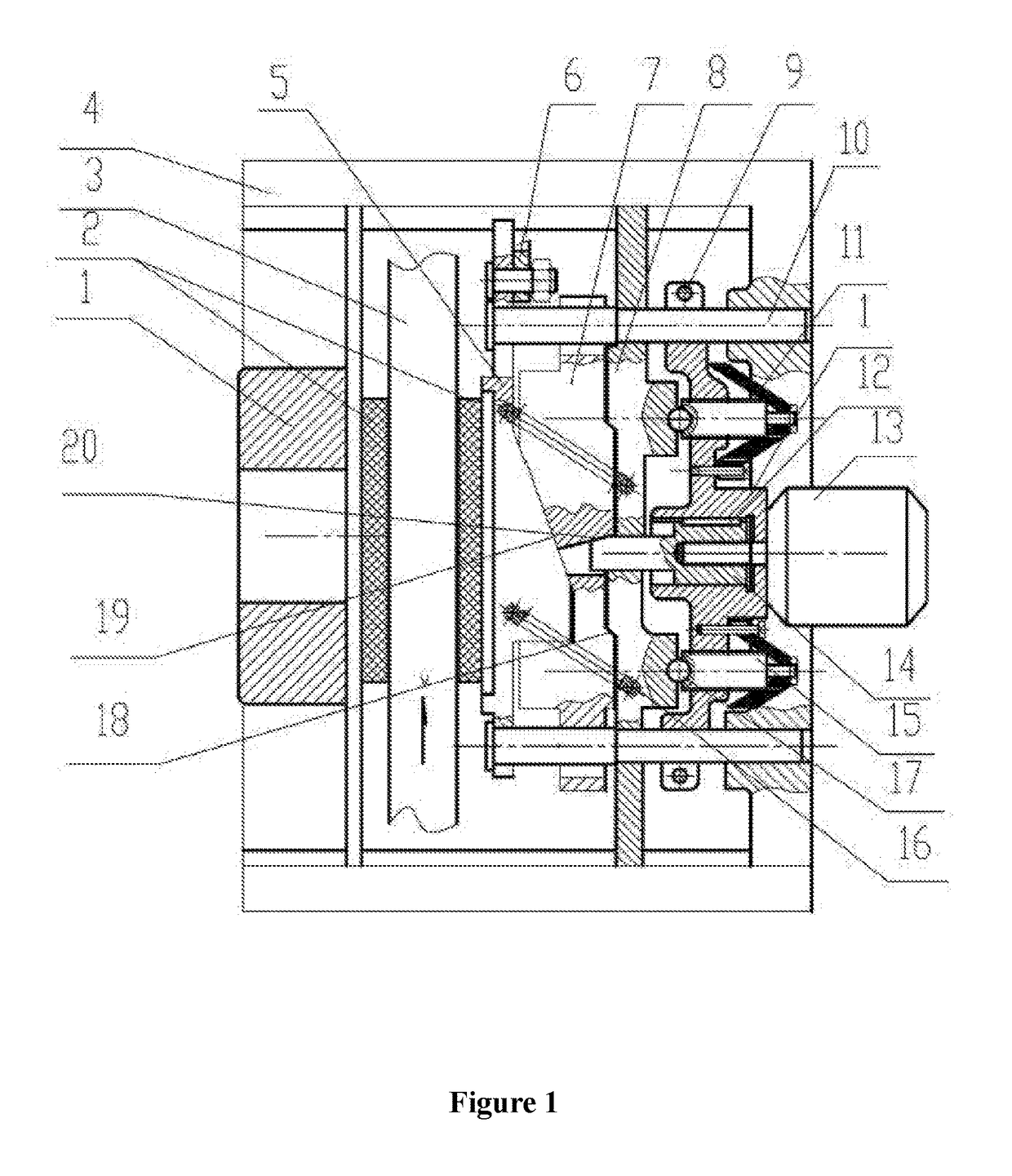
[0020]FIG. 1 is a cross section diagram of a floating-clamp-body-type high-energizing single-side double-inclined-surface disc brake for a car and an electric car.

[0021]Now according to FIG. 1, the structure and working principle of the brake will be introduced as follows. A brake disc (3) of the invention is completely the same as that of the common brake disc in the prior art. A brake shoe (2) is basically the same as the common brake shoe (also known as a brake sheet). Two brake shoes (2) are provided at the two sides of the brake disc (3). The brake disc (3) is secured to a wheel and can be rotated with the wheel. A machine body (1) is attached to a bracket (4) with a sliding way. The bracket (4) is fixed on a component which supports the wheel. One of the two brake shoes (2) is mounted at the left side of the machine body (1) and also slidably attached to the bracket (4). This is the same as the common brake. The other brake shoe is fixedly mounted on an energizing inclined boa...


PUM


Abstract

The invention relates to a disc-type brake which can use the energy of a transport machine during its traveling to brake, has a huge self-energizing action and is used for a motorcycle, a car, a truck, a train and an elevator. The brake has a very small control force (power), is simple and reliable and has a small volume. The brake is very easily designed as an electrically controlled disc-type brake system (EMB), the power and volume of an electrically controlled motor of the brake can be several times—more than a dozen of times less than that of an electrically controlled motor in the prior art, after its promotion, the brake can greatly improve the safety of the car and the motorcycle. The brake can reduce many parts, components and mechanisms and save much cost and bring us tremendous social and economic benefits and is a landmark brake.

Description

FIELD OF THE INVENTION[0001]The invention relates to a disc brake in the fields of traffic and transport machinery, such as a car, a motorcycle, a train, and an elevator.BACKGROUND[0002]Patent Application No. 201110291009.9, titled self-energizing disc brake, discloses a brake which solves a problem that the disc brake has no self-energizing effect, especially the big problem to control the self-energizing disc brake. It also solves the problem of the small self-energizing range of the self-energizing ratio (generally, it is only 1-4) of the brake. The self-energizing ratio (Efficiency Factor) can be increased by one times—dozens of times or even more. This greatly expands the use range of the disc brake. However, such self-energizing disc brake needs inclined surfaces to be arranged at two sides of the brake disc, thereby causing the disadvantages of bigger size, complicated structure and too many sealing parts.[0003]The disc brake on the car greatly improves the safety of the car....

Claims


Application Information

Patent Timeline
Patent Type & Authority Patents(United States)
IPC IPC(8): F16D55/08F16D65/18F16D55/48F16D55/225F16D121/24F16D125/66
CPCF16D65/18F16D55/225F16D55/48F16D2125/66F16D2121/24
Inventor CHEN, KUN
Owner CHENGDU SHUANGCHEN TECH CO LTD
Why Eureka
Try Eureka