Tension roller assembly for a belt drive

a technology of tension roller and belt drive, which is applied in the direction of agriculture, agriculture tools and machines, and machining, etc., can solve the problems of user injury, strong force on the user, and relatively little space for the belt to be removed, so as to reduce the risk of injury for the user, facilitate the operation, and reduce the risk of injury

Active Publication Date: 2018-04-10
BLUE LEAF I P INC
View PDF58 Cites 7 Cited by
  • Summary
  • Abstract
  • Description
  • Claims
  • Application Information

AI Technical Summary

Benefits of technology

[0016]In accordance with an aspect of the present invention, there is provided a tension roller assembly for a belt drive of a combine harvester which makes the transition between two different gear ratios of the belt drive easier to carry out. More specifically, there is provided a tension roller assembly for a belt drive of a combine harvester which can be operated with more ease and a lower risk of injury for the user.
[0017]In accordance with another aspect of the present invention, there is provided a tension roller assembly which shows a lower drop in tension of the belt in case of peak loads on the rotating drum, thereby reducing slipping of the belt at these peak loads.
[0018]In accordance with yet another aspect of the present invention, there is provided a tension roller assembly for a belt drive of a combine harvester which provides more clearance in the disengaged position for exchanging the belt.
[0034]An advantage is that due to the presence of the free-moving section, the user can switch the overcenter assembly with more ease, because the force of the spring is not present at the disengaged position. Further, there is an advantage in that the tension roller can be retracted further from the belt making the exchange of one belt for the other easier. A risk of injury is also reduced.
[0036]In an embodiment, a longer spring having a lower spring rate can be used than in the tension roller assembly of the prior art. This advantageously results in less reduction of the spring force when the belt stretches and results in a greater maximum torque.
[0055]In an embodiment, the belt drive is configured to be switched by a user between a low rotational speed, in particular somewhere in a range of 500-700 rpm, more in particular 640 rpm, and a high rotational speed, in particular somewhere between 1000 and 1200 rpm, more in particular 1100 rpm, wherein the belt drive provides a higher maximum torque in the low speed than in the high speed. The low and high rotational speed result in lower grain damage. For instance, corn and beans are more sensitive and require a lower rotational speed, whereas grain is less sensitive and may be processed at a higher rotational speed.

Problems solved by technology

First, the system is relatively unpractical for a user who wishes to switch the tension roller assembly between the engaged position and the disengaged position. The rotation of the overcenter assembly between the engaged position and the disengaged position is carried out under the force of the spring, and the spring force may be rather high. This results in a strong force on the user. The rotation is generally carried out with a wrench. Because of the high spring force, the hand of the user may get stuck between the wrench and the machine. In extreme cases, this may even lead to an injury of the user.
Further, the present assembly has relatively little room for the belt to be removed from the belt drive when the tension roller is in the disengaged position.
The limited space makes it difficult for a user to exchange one belt for the other belt.
The stretching may become particularly large when large, unevenly distributed packages enter the combine, causing high torque peaks on the belt drive.
This lowers the torque which can be applied by the belt drive and results in earlier slipping of the belt and, eventually, blockage of the dynamic feed roller.

Method used


Image

  • Tension roller assembly for a belt drive
  • Tension roller assembly for a belt drive
  • Tension roller assembly for a belt drive

Examples


Embodiment Construction

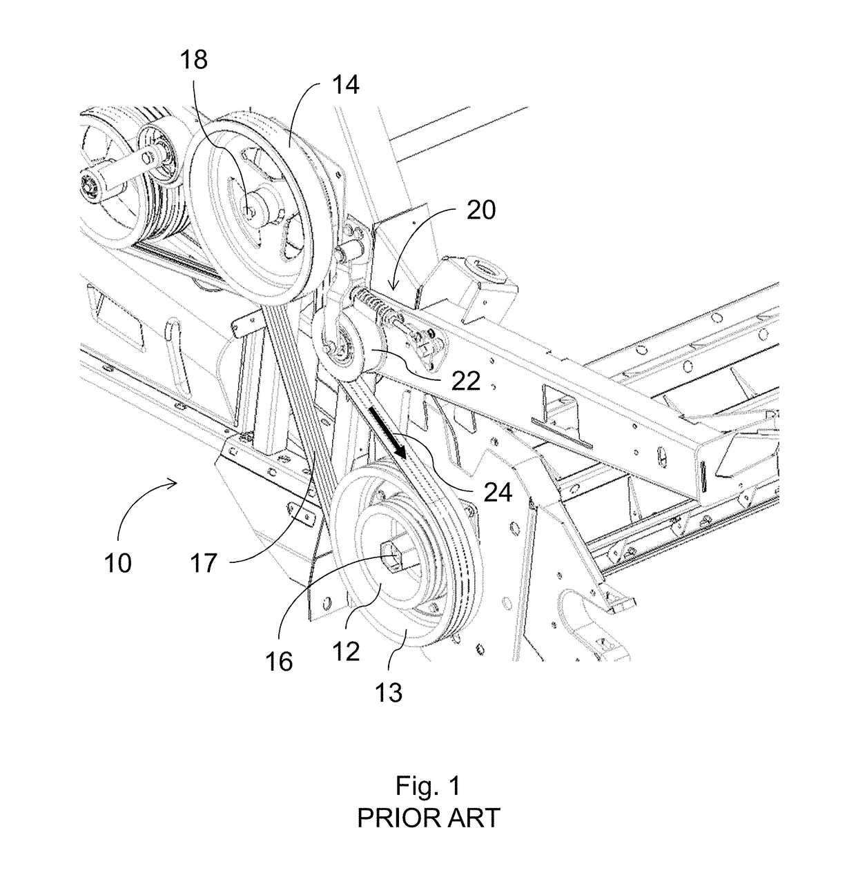
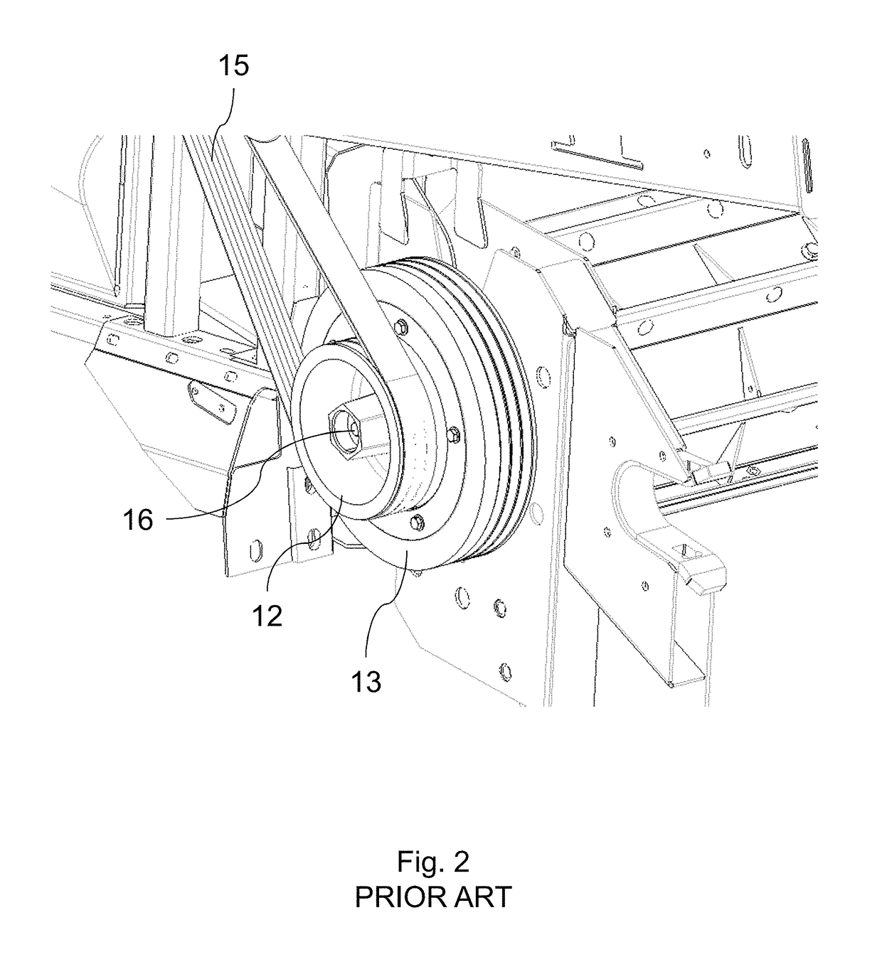
[0075]Turning to FIGS. 1 and 2, a belt drive 10 according to the prior art is shown. The belt drive 10 is used in a combine harvester for driving the dynamic feed roll. The shown belt drive is currently manufactured by the present applicant. The belt drive comprises a first driven pulley 12 and a second driven pulley 13. The first driven pulley 12 is smaller than the second driven pulley 13. The small and large driven pulley are provided on the same driven axis 16. The belt drive further comprises a driving pulley 14.

[0076]Turning in particular to FIG. 2, the belt drive has two gears. In the first gear, the small driven pulley 12 is used and the large driven pulley 13 is in an inoperative position. In this gear, the belt drive has a high speed and a low torque. When the belt drive needs to be switched to the low gear ratio, the belt 15 is removed. The large driven pulley 13 is moved from the inoperative position shown in FIG. 2 to the operative position shown in FIG. 1. This can be ...


PUM


Abstract

A tension roller assembly includes a tension roller, a pivotable support arm, a tension arm, a compression spring, a rod, first and second spring stops, a mounting plate, and an overcenter assembly connected to an end of the tension arm. The overcenter assembly connects the tension arm to the mounting plate. The overcenter assembly is configured to make a pivoting movement over a pivot trajectory between engaged and disengaged positions. The overcenter assembly further has a center position located between the engaged and disengaged positions. The pivot trajectory between the center position and the disengaged position is divided into a tensioned section in which the end stop does not engage the stop surface and the spring exerts a force on the overcenter assembly, and a free-moving section in which the end stop engages the stop surface and the spring does not exert any force on the overcenter assembly.

Description

CROSS REFERENCE TO RELATED APPLICATION[0001]This application claims priority to Belgium Application No. 2015 / 5525 filed Aug. 24, 2015, the contents of which are incorporated herein by reference.FIELD OF THE INVENTION[0002]The present invention relates to a tension roller assembly for a belt drive of a combine harvester for harvesting agricultural crops. The invention further relates to the belt drive comprising the tension roller assembly, to a combine harvester comprising the belt drive, and to a method of changing the gear ratio of a belt drive of a dynamic feed roll of the combine harvester.BACKGROUND OF THE INVENTION[0003]Belt drives comprising tension rollers for providing tension to the belt have been known for a long time and the application of such belt drives in combine harvesters has also been known for a long time. These belt drives are used to drive the threshing drum of a combine harvester. The threshing drum beats the cut crops to break the crop, and subsequently shake...

Claims


Application Information

Patent Timeline
Patent Type & Authority Patents(United States)
IPC IPC(8): F16H7/14F16H9/04F16H7/20A01F12/56A01D69/06F16H7/12F16H7/22F16H7/08
CPCF16H7/129A01D69/06A01F12/56F16H7/08F16H7/0827F16H9/04F16H7/20F16H2007/0893F16H2007/0806F16H2007/0842F16H2007/0865
Inventor BAILLIU, STIJNDUQUESNE, FRANKSOMERS, TOMVAN DE WEGE, CHARLOTTEVANCOILLIE, RUBEN
Owner BLUE LEAF I P INC
Why Eureka
Try Eureka