Threshold voltage detection circuit for OLED display device

a detection circuit and display device technology, applied in the field of display, to achieve the effect of eliminating the built-in electric field, reducing the number of output ends, and reducing the impact of oled current leakag

Active Publication Date: 2018-04-17
TCL CHINA STAR OPTOELECTRONICS TECH CO LTD
View PDF14 Cites 1 Cited by
  • Summary
  • Abstract
  • Description
  • Claims
  • Application Information

AI Technical Summary

Benefits of technology

[0007]The object of the present invention is to provide a threshold voltage detection circuit for OLED display device, able to detect the threshold voltage of the OLED and driver TFT of each sub-pixel driver circuit in a sub-pixel by sub-pixel manner, to reduce the current leakage of the OLED and driver TFT during the threshold voltage detection and improve the accuracy of the threshold voltage detection and prolong the lifespan of the OLED.
[0018]Compared to the known techniques, the present invention provides the following advantages: the present invention provides a threshold voltage detection circuit for OLED display device, providing multiplexers between the detection IC and the pixel driver unit so as to achieve sub-pixel by sub-pixel threshold voltage detection for the OLED and driver TFT of each sub-pixel driver circuit in the pixel driver unit, and reduce the number of output ends of the detection IC. Also, by using the second DC signal having the first and second levels with the first level smaller than the detection control signal and the second level larger than the detection control signal, during the detection for driver TFT, the second DC signal is switched to the second level to make the OLED reverse biased to reduce the impact of the OLED current leakage on the threshold voltage of the driver TFT, eliminate the built-in electric field of OLED and prolong the OLED lifespan; during the detection for OLED, the second DC signal is switched to the first level to make the OLED conductive and the data signal is at the same level as the detection control signal to guarantee the driver TFT is cut off to reduce the impact of the driver TFT current leakage on the threshold voltage of the OLED, and improve detection accuracy.

Problems solved by technology

At this point, the OLED D10 or the driver TFT is prone to current leakage, which affects the threshold voltage detection on the OLED D10 or the driver TFT.

Method used


Image

  • Threshold voltage detection circuit for OLED display device
  • Threshold voltage detection circuit for OLED display device
  • Threshold voltage detection circuit for OLED display device

Examples


Embodiment Construction

[0026]To further explain the technical means and effect of the present invention, the following refers to embodiments and drawings for detailed description.

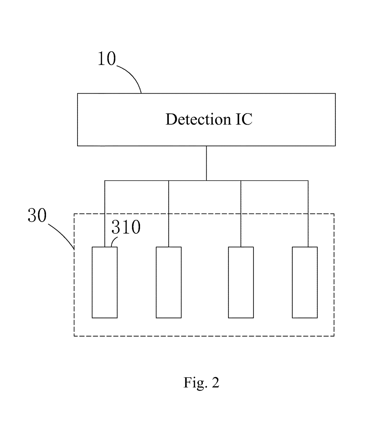
[0027]Refer to FIG. 3. The present invention provides a threshold voltage detection for OLED display device, which comprises: a detection IC 1, a plurality of multiplexers 2, and a plurality of pixel driver units 3.

[0028]Specifically, the detection IC 1 comprises: a plurality of output ends for outputting detection control signals Monitor, with each output end connected to a multiplexer 2 and each multiplexer 2 connected to a pixel driver unit 3; each pixel driver unit 3 comprises a plurality of sub-pixel driver circuits 31, each multiplexer 2 comprising a plurality of control units 21 corresponding respectively to the plurality of sub-pixel driver circuits 31.

[0029]Specifically, the input ends of the plurality of control units 21 of the same multiplexer 2 are all connected to the same output end of the detection IC 1, the contro...


PUM


Abstract

A threshold voltage detection circuit for OLED display device includes a multiplexer connected between a detection IC and each of multiple sub-pixel driver circuits of a pixel driver unit. A second DC signal having first and second levels with the first level smaller than the detection control signal and the second level larger than the detection control signal is fed to each of the sub-pixel driver circuits, such that during detection of threshold of a driver TFT, the second DC signal is switched to the second level and during detection of threshold of an OLED, the second DC signal is switched to the first level and a data signal is set at the same level as the detection control signal to achieve detection of the threshold voltages of the OLED and driver TFT of each sub-pixel driver circuit.

Description

BACKGROUND OF THE INVENTION1. Field of the Invention[0001]The present invention relates to the field of display, and in particular to a threshold voltage detection circuit for organic light-emitting diode (OLED) display device.2. The Related Arts[0002]The organic light emitting diode (OLED) provides the advantages of self-luminous, low driving voltage, high luminous efficiency, short response time, high clarity and contrast, wide viewing angle of near-180°, wide operating temperature range, enabling flexible display and large full-color display, and is recognized as the most promising technology.[0003]The driving types of OLED can be divided according to the passive matrix OLED (PMOLED) and active matrix OLED (AMOLED); i.e., the directly addressable and thin film transistor (TFT) array addressable; wherein the AMOLED has pixels arranged in an array layout, belonging to the active matrix, and high luminance efficiency; thus, is often used for high-resolution large-size display device...

Claims


Application Information

Patent Timeline
Patent Type & Authority Patents(United States)
IPC IPC(8): G09G3/36G09G3/325G09G3/3258
CPCG09G3/325G09G3/3258G09G2320/08G09G3/3233G09G2300/0452G09G2300/0842G09G2310/0297G09G2320/0295G09G2320/043G09G2320/045
Inventor WANG, ZHENLINGHWANG, TAIJIUN
Owner TCL CHINA STAR OPTOELECTRONICS TECH CO LTD
Why Eureka
Try Eureka