Therapeutic vibrating roller

Active Publication Date: 2018-05-15
HYPERICE IP SUBCO LLC
View PDF27 Cites 26 Cited by
  • Summary
  • Abstract
  • Description
  • Claims
  • Application Information

AI Technical Summary

Benefits of technology

[0008]An aspect in accordance with embodiments disclosed herein is a portable vibrating roller for therapeutic exercise. The roller comprises an outer roller structure comprising a firm, pliable foam material formed as a cylinder having a generally cylindrical outer circumference. The outer roller structure includes a plurality of grooves and ribs positioned around the outer circumference. The outer roller structure includes a hollow cylindrical bore extending longitudinally through the foam material. A vibration system comprising a shell is sized to fit within the hollow cylindrical bore of the outer roller structure. The shell has a first end cap and a second end cap. The shell encloses and supports a motor positioned proximate to one of the first end cap and the second end cap. The motor is responsive to applied power to rotate an output shaft at a selected one of a plurality of angular velocities. A battery is positioned proximate to the other of the first end cap and the second end cap. An eccentric mass is coupled to the output shaft of the motor to rotate and cause vibration when the output shaft is rotated by the motor. The eccentric mass is positioned at a location approximately midway between the first end cap an

Problems solved by technology

The rotating eccentric mass causes vibration.
An eccentric mass is coupled to the output sha

Method used


Image

  • Therapeutic vibrating roller
  • Therapeutic vibrating roller
  • Therapeutic vibrating roller

Examples


Embodiment Construction

[0026]The improvements to the therapeutic roller are disclosed herein with respect to exemplary embodiments of a system and a method. The embodiments are disclosed for illustration of the system and the method and are not limiting except as defined in the appended claims. Although the following description is directed to a particular embodiment of a vibrating therapeutic roller, it should be understood that the disclosed system and method can be applied to other embodiments of therapeutic vibrating rollers.

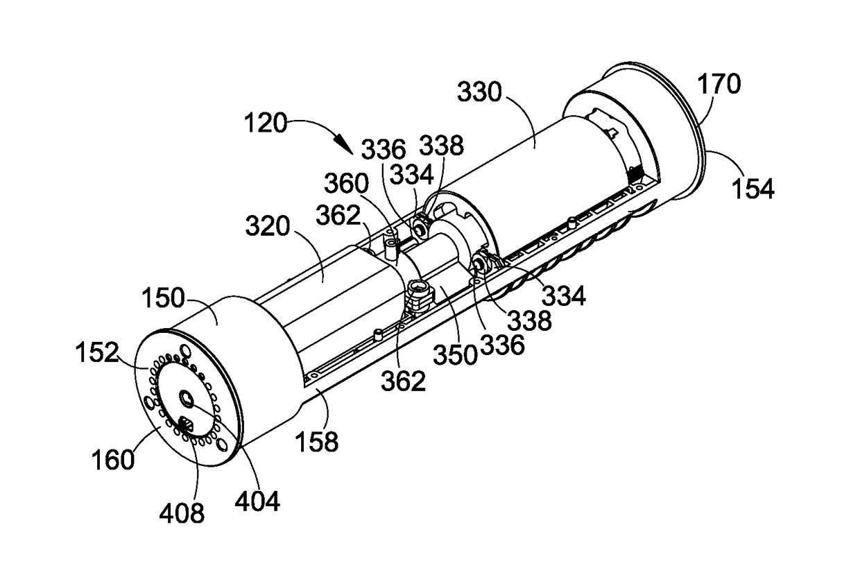
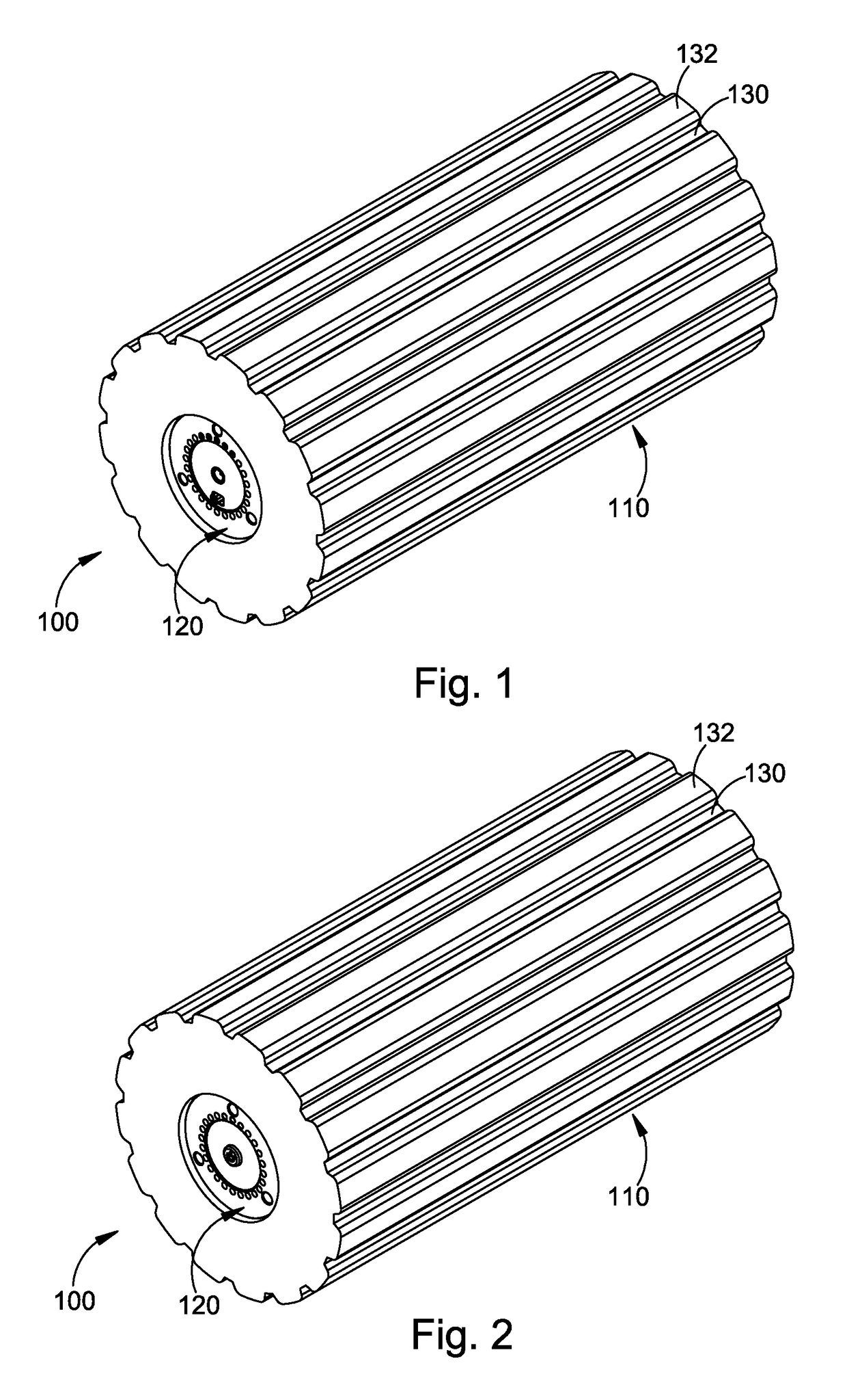
[0027]FIG. 1 and FIG. 2 illustrate a front perspective view and a rear perspective view, respectively, of a vibrating roller 100, which comprises a generally cylindrical outer roller structure 110 and an internal vibration generator 120 housed within the outer roller structure.

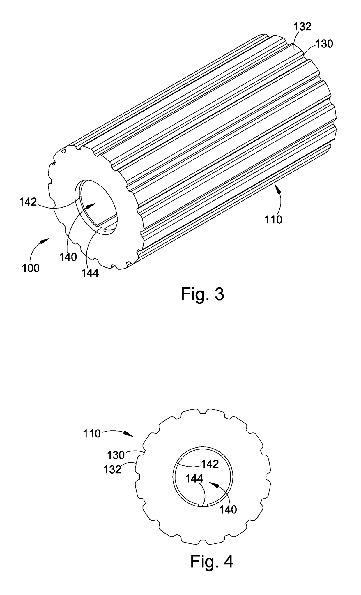
[0028]As illustrated in FIGS. 3 and 4, the outer roller structure 110 comprises a pliable foam material, such as, for example, a closed-cell polyethylene foam. For example, the foam material may comprises MI...


PUM


Abstract

A portable vibrating roller includes an outer roller structure having a plurality of grooves and ribs. A hollow cylindrical bore extends longitudinally through the shell. A vibration system having a first end cap and a second end cap fits within the bore. A battery positioned within the shell near one end cap provides electrical power to a motor positioned within the shell near the other end cap to cause the motor to rotate an output shaft at a plurality of angular velocities to rotate an eccentric mass located approximately midway between the two end caps. The rotating eccentric mass causes vibration. A motor control circuit receives input power from a battery and selectively provides output power to the motor in response to the operation of a switch on the first end cap. The output power is varied to control the angular velocity of the output shaft of the motor and to thereby control a frequency of vibration caused by the eccentric mass.

Description

RELATED APPLICATIONS[0001]The present application claims the benefit of priority under 35 USC § 119(e) to U.S. Provisional Application No. 61 / 942,929, filed on Feb. 21, 2014, which is incorporated by reference herein.BACKGROUND OF THE INVENTIONField of the Invention[0002]The present invention is in the field of therapeutic devices, and, more particularly, is in the field of rollers for kneading muscles and other tissue.Description of the Related Art[0003]Foam rollers are used to provide tissue mobilization, which provides benefits such as improvement of muscle flexibility and tightness, reduction of lactic acid in the muscles, reduction of muscle fibrosis (adhesions and scar tissue), and reduction of risk of injury. Increased muscle tone and tightness can be achieved by applying pressure to the muscles via the roller.[0004]Vibrating foam rollers provide the additional benefit of increasing blood flow, increasing oxygen and nutrient consumption by muscles and improving regeneration o...

Claims


Application Information

Patent Timeline
IPC IPC(8): A61H23/02A61H15/00
CPCA61H23/02A61H2015/0071A61H15/00A61H23/0263A61H2015/0014A61H2201/0214A61H2201/0242A61H2201/1695A61H2201/0153
Inventor MARTON, ROBERTKATZ, ANTHONY
Owner HYPERICE IP SUBCO LLC
Why Eureka
Try Eureka