Switch driving device and switch driving method

a driving device and switch technology, applied in the direction of electronic switching, pulse technique, power conversion system, etc., can solve the problems of complicated circuit configuration, increased cost, large size of the entire device, etc., and achieve the effect of simple and compact configuration

Active Publication Date: 2018-05-15
TDK CORPARATION
View PDF11 Cites 0 Cited by
  • Summary
  • Abstract
  • Description
  • Claims
  • Application Information

AI Technical Summary

Benefits of technology

[0007]The switch driving device described in the above-described Japanese Patent No. 4945218, however, employs a transformer to generate the negative voltage to be applied to the gate of the switching element. This causes the problems of a larger size of the entire device and an increased cost. Moreover, the switch driving device described in the above-described Japanese Patent No. 4916964 separately requires switching elements (a p-channel MOSFET 107, an n-channel MOSFET 108, and an n-channel MOSFET 109) for controlling the charging and discharging (the storage and emission of charge) of a negative voltage generating capacitor 104. This causes the problems of a complicated circuit configuration and an increased cost.
[0009]The latest-generation switching elements, which employ semiconductor such as SiC or GaN instead of conventionally-used Si, are becoming pervasive in recent years. These elements, however, have a higher rate of occurrence for the self-turn-on phenomenon due to their capability of high-speed driving and their low threshold voltage and input and output capacitance. Accordingly, a switch driving device capable of preventing the self-turn-on phenomenon with a simple and compact configuration is demanded also for the purpose of effectively using these latest-generation switching elements.
[0010]The present invention has been made in view of the aforementioned problems. It is an object of the invention to provide a switch driving device and a switch driving method capable of preventing the self-turn-on phenomenon with a simple and compact configuration.
[0017]The switch driving device and the switch driving method according to the present invention can provide an advantageous effect of preventing the self-turn-on phenomenon with the simple and compact configuration.

Problems solved by technology

This causes the problems of a larger size of the entire device and an increased cost.
This causes the problems of a complicated circuit configuration and an increased cost.
Furthermore, since a drive voltage of a high-side MOSFET 102 is generated by a bootstrap circuit (a boot diode 113 and a boot capacitor 127) in the switch driving device described in the above-described Japanese Patent No. 4916964, it is difficult to provide on the high side a negative voltage generating circuit similar to that on the low side.
These elements, however, have a higher rate of occurrence for the self-turn-on phenomenon due to their capability of high-speed driving and their low threshold voltage and input and output capacitance.

Method used


Image

  • Switch driving device and switch driving method
  • Switch driving device and switch driving method
  • Switch driving device and switch driving method

Examples


Embodiment Construction

[0026]An embodiment of the present invention will now be described below with reference to the accompanying drawings. Note that the depiction of some components is omitted or simplified in each figure for ease of understanding.

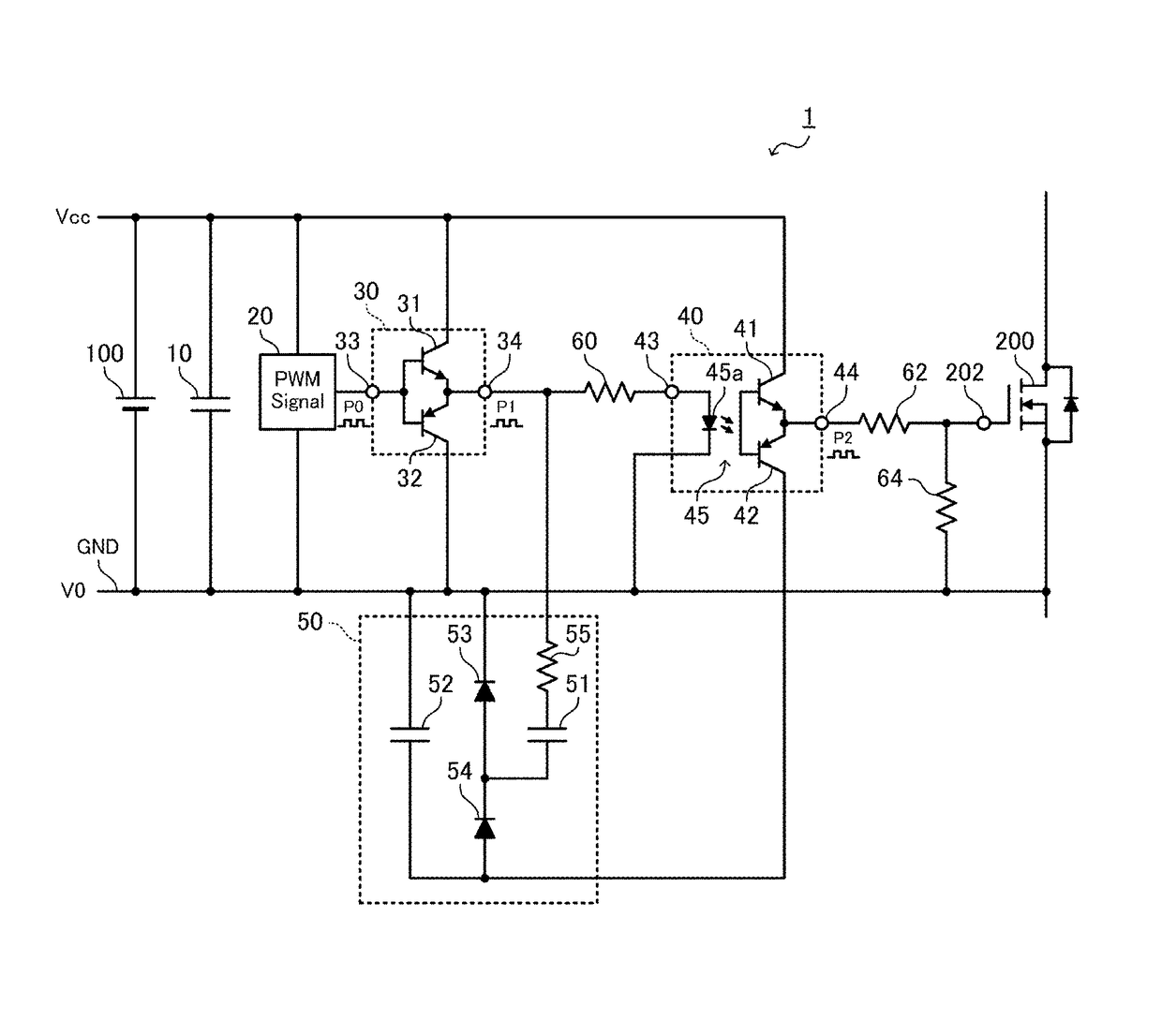
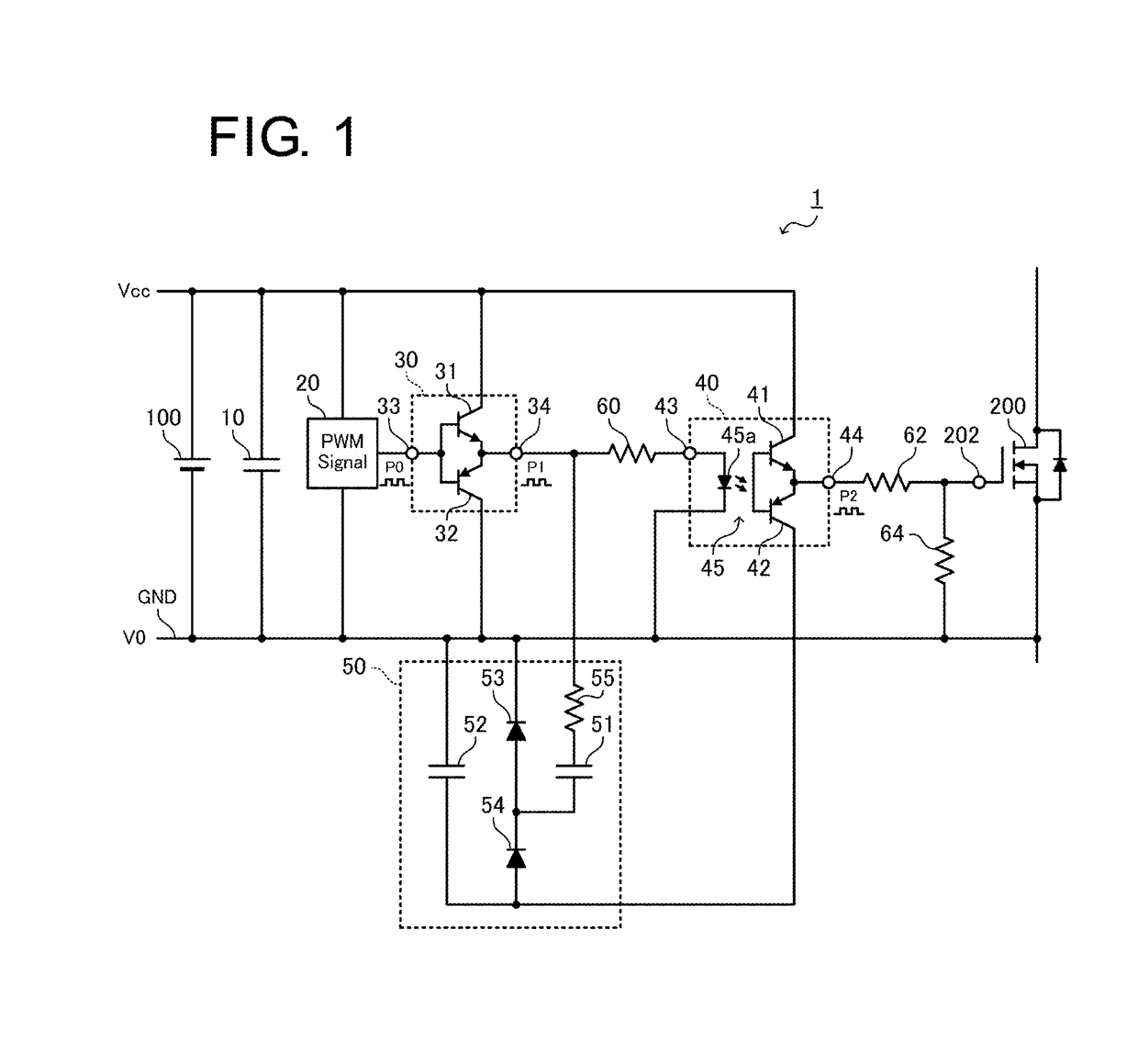
[0027]FIG. 1 is a circuit diagram showing a configuration of a switch driving device 1 according to the present embodiment. The switch driving device 1 of the present embodiment is provided to switching power supply devices such as a wide variety of converters or inverters. The switch driving device 1 is configured to drive (i.e., switching between ON and OFF) a switching element 200, which is constructed of a MOSFET, by an input voltage Vcc input from a DC power supply 100 with a negative side thereof being connected to ground GND. As illustrated in FIG. 1, the switch driving device 1 includes an input capacitor 10, a pulse generating unit 20, a first signal output unit 30, a second signal output unit 40, and a negative power supply generating unit 50.

[0028]T...


PUM


Abstract

There are provided a switch driving device and a switch driving method capable of preventing a self-turn-on phenomenon. The switch driving device includes: a first signal output unit configured to output a pulsed first driving signal from a first output terminal thereof; a second signal output unit configured to output a pulsed second driving signal to a control terminal of a switching element from a second output terminal thereof; and a negative power supply generating unit configured to generate a negative voltage relative to a ground voltage and bias a low level of the second driving signal toward a negative side by the negative voltage. The negative power supply generating unit includes: a first capacitor configured to store charge by the first driving signal; and a second capacitor configured to generate the negative voltage across terminals thereof by the transfer of the charge from the first capacitor.

Description

BACKGROUND OF THE INVENTION[0001]1. Field of the Invention[0002]The present invention relates to a switch driving device and a switch driving method for driving a switching element in a power supply device such as a DC-DC converter, for example.[0003]2. Description of the Related Art[0004]As power supply devices such as DC-DC converters, for example, switching power supply devices in which a switching element (semiconductor switch) such as a metal oxide semiconductor field effect transistor (MOSFET) or an insulated gate bipolar transistor (IGBT) is driven by a switch driving device (drive circuit) so as to convert power have been widely used.[0005]In such a switching power supply device, the problem of a self-turn-on phenomenon in which a switching element in an OFF state is mistakenly turned ON may arise, for example, when the switching element is driven at high speed. In this self-turn-on phenomenon, a drain-source voltage in an OFF state sharply rises along with the high-speed dr...

Claims


Application Information

Patent Timeline
Patent Type & Authority Patents(United States)
IPC IPC(8): H03K17/04H03K17/16H03K17/567H03K19/0175H03K17/06
CPCH03K17/567H03K17/063H03K19/017509H03K17/162H03K2017/066H02M1/08
Inventor IWAYA, KAZUKI
Owner TDK CORPARATION
Why Eureka
Try Eureka