Capillary network devices and methods of use

a network device and capillary technology, applied in fluid controllers, laboratory glassware, chemistry apparatus and processes, etc., can solve the problems of deteriorating rbcs, increasing acidity and hyper-osmolality, and hemolysis, and reducing the permeability of the capillary network

Active Publication Date: 2018-05-22
THE ADMINISTRATORS OF THE TULANE EDUCATIONAL FUND +1
View PDF27 Cites 2 Cited by
  • Summary
  • Abstract
  • Description
  • Claims
  • Application Information

AI Technical Summary

Problems solved by technology

These effects ultimately result in RBC apoptosis, hemolysis, and the accumulation of extracellular free hemoglobin in the bag.
Oxidative damage to the RBCs increases the acidity and hyper-osmolality of the suspending storage media (with an end pH of ˜6.6 and osmolality of ˜320 mmol / kg at 6 weeks); the deteriorating RBCs are bathed in an increasingly toxic media.
The RBC expends ATP in an attempt to repair its cellular components; however, without a nucleus, the protein synthesis needed to continually replace key enzymes within the RBC cannot occur throughout the duration of storage, so the cells become increasingly rigid and fragile.
Storage induced biochemical and mechanical changes within the RBCs reduce their ability to undergo physiologically relevant deformations, increasing the overall viscosity of blood and decreasing microvascular perfusion (e.g., at bifurcations, non-deformable RBCs may bypass the narrow microchannels for the larger, high flow microchannels or even plug the narrow microchannels as seen in our devices) resulting in poor tissue oxygenation.
Because of this storage-induced deterioration, stored RBCs may be unable to maintain adequate blood flow in microchannels and deliver oxygen as effectively as their fresh counterparts.
If transfused, they may be unable to improve perfusion of the microvascular networks and oxygenation of tissues and, thus, may reduce the clinical efficacy of RBC transfusions.
Although very informative for studying the RBC rheologic response under well-defined conditions, these conventional approaches have several common limitations: 1) each technology is focused on a narrow subset from the wide spectrum of deformations experienced by RBCs in the microcirculation, 2) RBC properties are examined under nonphysiological conditions (e.g., at ultralow Hct or while suspended in high-viscosity buffers), and 3) the effects of the architecture of microvascular networks are not taken into account.
However, direct validation of microvascular behavior using in vivo experiments may be prohibitively complex or even impossible.
However, current instrumentation does not provide sufficient and adequate means to obtain actual information regarding the flow of blood in capillary network channels.

Method used


Image

  • Capillary network devices and methods of use
  • Capillary network devices and methods of use
  • Capillary network devices and methods of use

Examples


example 1

Network Device Design

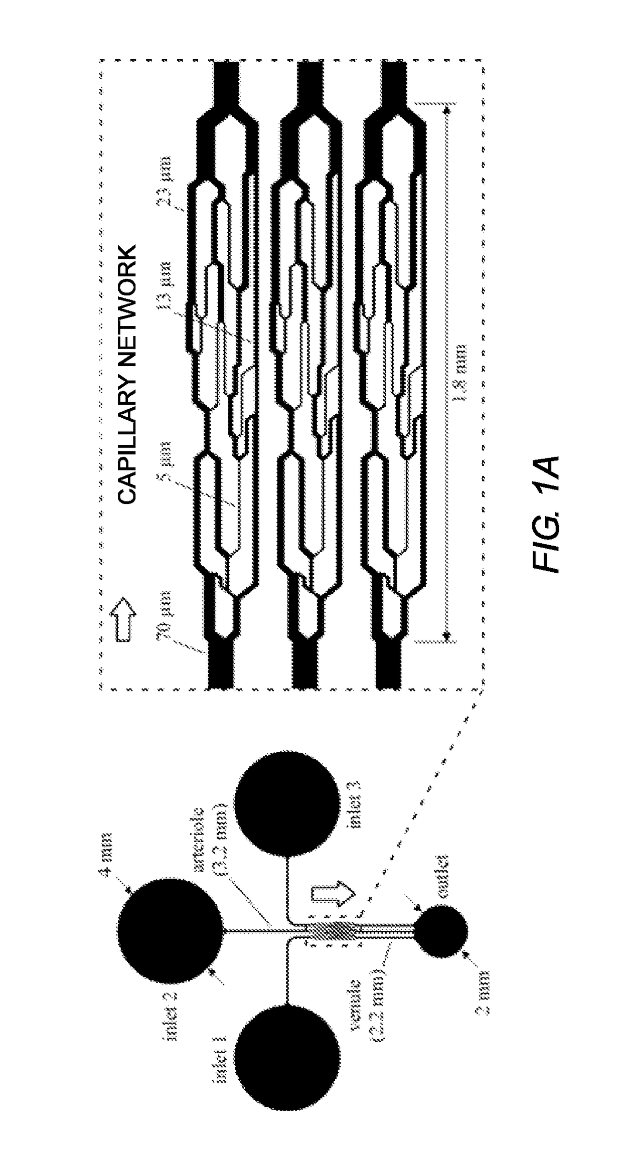
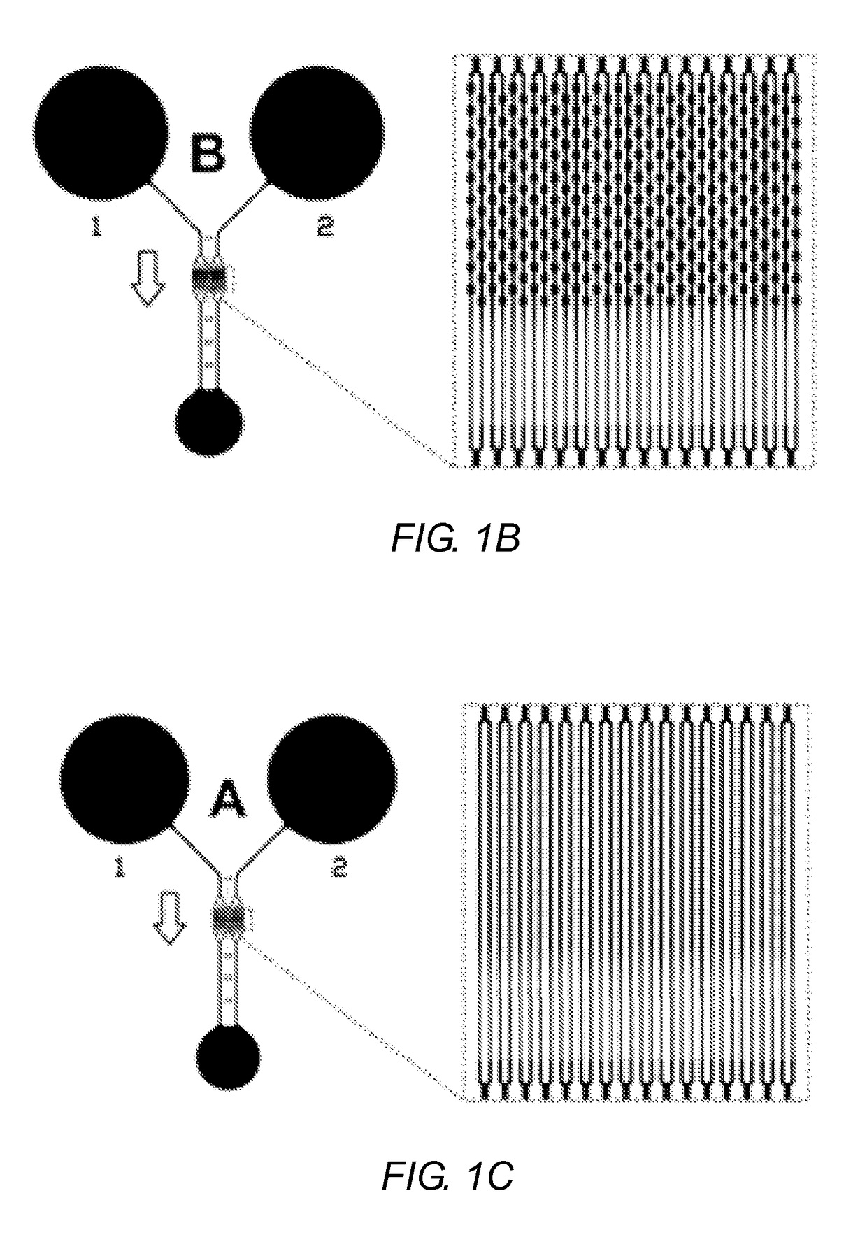
[0103]FIGS. 1A-1C show a schematic illustration of the three microfluidic devices according the present disclosure. FIG. 1A shows an aspect of a CND designed to mimic the morphological pattern of a mesenteric microvasculature. CNDs designed to mimic microvasculature may be referred to as an AMVN (Artificial Microvascular Network) device. FIG. 1B shows an alternative Capillary Network Device A (CND-A) having tapered microchannels as illustrated in FIG. 1D. The CND shown in FIG. 1C is another aspect of a Capillary Network Device (CND-B) having a series of repeating constrictions and expansions as illustrated in FIG. 1E.

example 1a

rtificial Microvascular Network (AMVN) Device

[0104]The AMVN device has three identical network units connected by 70 μm inlet microchannels and one common outlet port connected via 70 μm output microchannels. The channels are 5 μm deep. Each network consists of a 70 μm inlet microchannel that bifurcates two to three times to create one or more 5 μm interconnecting microchannels. The bifurcated channels then converge to microchannels of 13 μm and 23 μm before converging to the 70 μm output microchannel (FIG. 1A inset).

example 1b

Network Device A (CND-A) and B (CND-B)

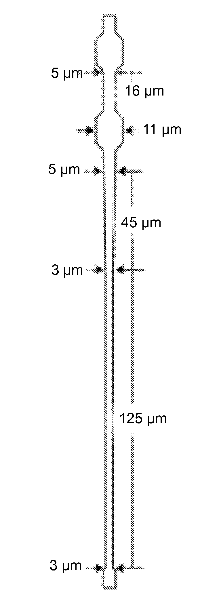
[0105]CND-A illustrated in FIG. 1B and CND-B illustrated in FIG. 1C are designed to be identical except for the shape of their microchannel elements (the microchannels located in the center of the networks). Each device consists of two identical network units with two independent inlet ports and one common outlet port. Each network unit consists of a 70 μm inlet microchannel connecting the inlet port to a parallel array of 32 microchannel via a series of bifurcating junctions; each capillary array drains through a series of junctions to converge into a single 70 μm outlet microchannel. The microchannel arrays of FIGS. 1B and 1C are depicted in FIGS. 1D and 1E, respectively. In FIG. 1B, the tapered microchannels of CND-A comprise a 330 μm long, 5 μm wide straight portion followed by a 45 μm long portion gradually tapering to a 3 μm wide section that further extends to a length of 125 μm on the output side (FIG. 1D). In FIG. 1C, the microchannels ...


PUM

PropertyMeasurementUnit
cross-sectional widthaaaaaaaaaa
lengthaaaaaaaaaa
widthaaaaaaaaaa

Abstract

Artificial microvascular network (AMVN) devices are provided and related methods of making and methods of using such devices are provided. The present disclosure generally relates to an AMVN device comprising a substrate including a capillary network configured so as to simulate those actually encountered in the circulation of various humans and animal model systems. In certain aspects, the AMVN devices may be used, e.g., to investigate the effect of storing RBCs under aerobic and anaerobic conditions. However, the use of such AMVN devices is not so limited.

Description

INCORPORATION BY REFERENCE[0001]This application is a U.S. National Stage Application of PCT / US2013 / 042314, filed on May 22, 2013, which claims the benefit of the filing date of U.S. Provisional Application 61 / 650,283, filed on May 22, 2012. All of the aforementioned applications are incorporated herein by reference in their entireties.FIELD OF THE DISCLOSURE[0002]The present disclosure relates to Capillary Network Devices (CNDs). More particularly, the present invention relates to micro-scale devices that simulate the capillary networks and their physiological function (artificial microvascular devices).BACKGROUND OF THE INVENTION[0003]Human red blood cells in vivo are in a dynamic state. In whole blood, white blood cells are normally present in the range between 4,300 and 10,800 cells / μL and the normal RBC range at sea level is 5.4 million / μL (±0.8) for men and 4.8 million μL (±0.6) for women. The red blood cells contain hemoglobin, the iron-containing protein that carries oxygen ...

Claims


Application Information

Patent Timeline
Patent Type & Authority Patents(United States)
IPC IPC(8): G01N33/80B01L3/00
CPCG01N33/80B01L3/5027B01L3/502715B01L2300/0867B01L2300/0838B01L2300/0861B01L3/502761B01L3/502746B01L2400/086
Inventor YOSHIDA, TATSUROSHEVKOPLYAS, SERGEY S.BURNS, JENNIE M.
Owner THE ADMINISTRATORS OF THE TULANE EDUCATIONAL FUND
Why Eureka
Try Eureka