Thrust reverser unit having both nested cascades translating linearly and only one cascade rotational

a thrust reverser unit and cascade technology, which is applied in the direction of engine fuction, machine/engine, engine manufacture, etc., can solve the problems of increasing fuel consumption, occupying significant space in the gas turbine engine, and the size of current trus may not be compatible with the desired reduction in the size of the nacelle, etc., to achieve the effect of reliable arrangement and robustness

Inactive Publication Date: 2018-05-29
ROLLS ROYCE DEUT LTD & CO KG
View PDF15 Cites 5 Cited by
  • Summary
  • Abstract
  • Description
  • Claims
  • Application Information

AI Technical Summary

Benefits of technology

[0012]It is therefore desirable to provide a TRU with improved efficiency in one or both of the stowed and deployed configurations, which can be made to be smaller and lighter. Any TRU must also be robust and reliable, both during deployment and retraction, as well as in use.
[0022]Providing both the first and the second elements with flow passages therein may be a particularly efficient arrangement for using the momentum of the flow through the bypass duct to generate a decelerating force on the engine. For example, both the first and the second elements may contribute to turning the flow towards the upstream direction (relative to the flow through the bypass duct) in order to provide a decelerating force to the engine. This results in a compact and / or lightweight TRU.
[0029]The flow passages in the first element may be defined by flow turning vanes. The flow turning vanes of the first element may be arranged (for example shaped and / or angled) so as to turn the flow towards the second element when in the deployed configuration, which may be away from the longitudinal axis of the engine and / or towards the radial direction. This may contribute to reducing the component of momentum of the bypass flow in the (downstream) axial direction of the engine, so as to provide a decelerating force to the engine.
[0034]In the stowed configuration, the flow turning vanes of the first element may be nested (or stacked) within the flow turning vanes of the second element. This may provide a particularly compact arrangement when in the stowed configuration.
[0038]The TRU may also comprise a stop element fixed to the first part of the nacelle, the stop element being arranged to engage the slidable link member at a second end of the slidable link member at a predetermined position of the first element relative to the first part of the nacelle. Accordingly, further translation of the slidable link member, and thus the first element to which it is attached, relative to the first part of the nacelle may be prevented when the slidable link member engages the stop element.
[0044]The thrust reverser unit may comprise a support beam extending between the first element and the second element. Such a support beam may be rotatably fixed at a first end to one of the first and the second elements and slidably engaged with the other of the first and the second elements. Accordingly, the support beam may rotate relative to the first and second elements as they rotate relative to each other to allow the first element to adopt its deployed position. When the thrust reverser unit is in the deployed configuration, the support beam may extend in a direction that is substantially perpendicular to the body of the first element. Accordingly, the support beam may transmit, in use, aerodynamic load from the first element to the second element. This may be a particularly robust and reliable arrangement.

Problems solved by technology

This extra weight leads to increased fuel consumption.
Furthermore, the TRUs also occupy significant space within the gas turbine engine.
For example, TRUs conventionally occupy significant space in the nacelle of a turbofan gas turbine engine when they are stowed during flight.
The size of current TRUs may not be compatible with the desired reduction in the size of nacelles.
However, the drag link 52 and its associated joints and hinges, of which there may be several circumferentially spaced around the bypass duct, extends across the bypass duct even when the TRU 50 is in the stowed configuration, thereby causing losses in the flow through the bypass duct.
For example, in the stowed configuration, the drag links 52 and the associated hinges, steps and gaps where they are joined to the other parts of the engine, create aerodynamic loss during normal, forward flight conditions, which leads to increased fuel consumption.
Flow also tends to stagnate and recirculate in the region 78 in front of the blocker door, generating further losses.
Additionally, the flow that has not separated has different angles along the length of the cascade 56, meaning either that the design of the elements in the cascade 56 has to be complex and thus expensive, or that the cascade 56 does not operate at optimum efficiency along its length.
Any loss or inefficiency in the flow when the TRU 50 is in the deployed configuration means that the TRU 50 must be bigger and / or heavier to generate a given deceleration, leading to a further increase in fuel consumption.

Method used


Image

  • Thrust reverser unit having both nested cascades translating linearly and only one cascade rotational
  • Thrust reverser unit having both nested cascades translating linearly and only one cascade rotational
  • Thrust reverser unit having both nested cascades translating linearly and only one cascade rotational

Examples


Embodiment Construction

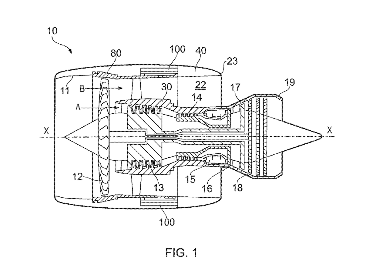
[0064]With reference to FIG. 1, a ducted fan gas turbine engine generally indicated at 10 has a principal and rotational axis X-X. The engine 10 comprises, in axial flow series, an air intake 11, a propulsive fan 12, an intermediate pressure compressor 13, a high-pressure compressor 14, combustion equipment 15, a high-pressure turbine 16, and intermediate pressure turbine 17, a low pressure turbine 18 and a core engine exhaust nozzle 19. The engine also has a bypass duct 22 and a bypass exhaust nozzle 23. The bypass duct 22 may be a generally annular passage, having a core case 30 at its inner radius, and a nacelle 40 and / or a fan case 80 at its outer radius.

[0065]The gas turbine engine 10 works in a conventional manner so that air entering the intake 11 is accelerated by the fan 12 to produce two air flows: a first air flow A into the intermediate pressure compressor 13 and a second air flow B which passes through the bypass duct 22 to provide propulsive thrust. The intermediate pr...


PUM


Abstract

A thrust reverser unit (TRU) 100 for a gas turbine engine 10 is provided that has first and second cascade elements 110, 120. In a stowed configuration, both the first and second cascade elements, and the operating mechanism, are located inside the nacelle 40, meaning that the TRU has no detrimental impact on the flow through the bypass duct 22. In the deployed configuration, the first cascade element 110 extends across the bypass duct 22. The first cascade element 110 has flow passages 112 that allow the flow to pass through, redirecting the flow towards the second cascade element 120. The second cascade element 120 further turns the flow so as to provide decelerating reverse thrust.

Description

CROSS-REFERENCE TO RELATED APPLICATIONS[0001]This application is based upon and claims the benefit of priority from British Patent Application Number 1314527.1 filed 14 Aug. 2013, the entire contents of which is incorporated by reference.BACKGROUND OF THE INVENTION[0002]1. Field of the Disclosure[0003]The invention relates to a thrust reverser unit for a gas turbine engine. In particular, the invention relates to a compact thrust reverser unit for turbofan gas turbine engines.[0004]2. Description of the Related Art[0005]Many modern aircraft use thrust reverser units (TRUs) to assist with the deceleration of an aircraft after landing. Such units operate by reversing the direction of at least a part of the flow passing through the engine, thereby generating a decelerating thrust. TRUs may be used in addition to conventional brakes provided on aircraft wheels. Such conventional brakes may be very efficient, but in adverse conditions, such as a wet or icy runway, the coefficient of fric...

Claims


Application Information

Patent Timeline
Patent Type & Authority Patents(United States)
IPC IPC(8): F02K1/76F01D9/04F02K1/70F01D17/10F01D25/24F02K1/72
CPCF02K1/70F01D9/041F01D17/105F01D25/24F02K1/72F02K1/763F05D2260/50F05D2220/36F05D2240/12F05D2240/129F05D2240/40F05D2250/62F05D2220/32
Inventor TEIA DOS SANTOS MENDES GOMES, LUIS DANIEL
Owner ROLLS ROYCE DEUT LTD & CO KG
Why Eureka
Try Eureka