Infrared transparent film

Active Publication Date: 2018-06-05
QINETIQ LTD
View PDF15 Cites 10 Cited by
  • Summary
  • Abstract
  • Description
  • Claims
  • Application Information

AI Technical Summary

Benefits of technology

[0047]In WO 2009/112810, a coloured thermal infrared transparent layer can be applied by a coating method. However, the inventors have found that sawtooth films having a conformal coating of this type have a number of important disadvantages, including poor abrasion resistance and susceptibility to contamination with surface dirt and/or water. In the preferred embodiment of the invention, the problems are overcome by providing a thin film, thermally reflective material comprising a structured infrared reflective layer and an infrared transparent layer provided on one surface thereof, wherein the infrared transparent layer comprises a polymer matrix with a pigment dispersed therein, the infrared reflective surface being structured to provide directional reflection and the infrared transparent layer forming a non-conformal coating on the surface of the structured reflective surface. The outer surface of the infrared transparent layer can be planar or substantially planar (perhaps with a degree of slight curvature due to the underlying textured reflective surface). If required, the outer surface of the polymer can be textured, for ex

Problems solved by technology

As a result, identification markings designed for use at visible wavelengths and/or near infrared wavelengths have little or no contrast with the background at thermal infrared wavelengths and are not generally discernible when viewed through thermal imagers.
The inventors have found that thin film identification devices according to WO 2006/016094 and WO 2009/112810 have a number of important drawbacks, includin

Method used


Image

  • Infrared transparent film
  • Infrared transparent film
  • Infrared transparent film

Examples


Example

Example 1

[0100]A Beige coloured infrared transparent film was provided by mixing a 2:1 blend of Masterbatch with Ipethene® 320 (LDPE) as follows:[0101]Masterbatch / Ipethene 320 blend at 92% by mass[0102]UVR95 UV stabiliser at 5% by mass[0103]AR2435 Desiccant @ 3% mass

[0104]This resulted in a pigment loading of ˜7.4%.

[0105]The Masterbatch is an approximately 8% wt / wt blend of zinc sulphide, cadmium sulphide (CI Pigment Yellow 35), cadmium sulphoselenide (CI Pigment Red 108) and barium sulphate (CI Pigment White 21).

[0106]After blending, the masterbatch was blown to form a 50 micron lay-flat film.

[0107]In general, the mixture of pigments can be selected to provide a particular colour. In turn, the colour is selected based on the application and / or the field of use. A bright colour is typically selected for high visibility and / or detection. For low visibility and / or camouflage, the colour is typically chosen to match the background.

Example

Example 2

[0108]A coloured, infrared transparent material suitable for use in an identification device was fabricated by applying a vapour deposited, 100 nm layer of aluminium to the coloured polymer film described in Example 1. A pressure sensitive adhesive was then applied to the aluminium layer, followed by a backing paper.

Example

Example 3

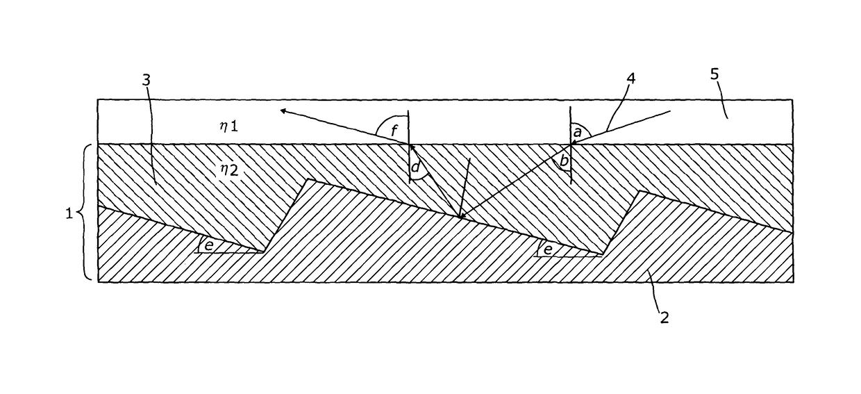
[0109]A thin film, thermally reflective material suitable for use in an identification device was fabricated by co-extruding the film layer described in Example 1 with a 100 micron thick polyethylene terephthalate (PET) layer with a 50 micron deep sawtooth texture formed in UV cured acrylic resin (14° major facet angle, 84° minor facet angle, 82° apex angle) coated with a 100 nm layer aluminium, thereby producing a thermally reflective directional reflector having a non-conformal coating. A pressure sensitive adhesive was subsequently applied to the PET surface opposite the colour layer followed by a backing paper.

[0110]The SEM of FIG. 7a shows the material.


PUM


Abstract

The invention relates to a thermal infrared transparent polymer film suitable for use in an identification device, said film comprising an infrared transparent polymer matrix with a pigment dispersed therein, wherein the thickness of the polymer film is greater than 30 micron and wherein the polymer film has an average transmission in the thermal infrared of greater than or equal to 0.5. Preferably, the pigment comprises an inorganic material. There is further provided a thin film, thermally reflective material (20) comprising the afore-mentioned infrared transparent film (21) and an infrared reflective layer provided on one surface thereof (22).

Description

FIELD OF THE INVENTION[0001]The present invention relates to a coloured, infrared transparent polymer film, particularly a polymer film which is transparent in the thermal infrared waveband. The invention also relates to thin film, thermally reflective materials and identification devices comprising said materials, and methods of making thermally reflective materials.BACKGROUND OF THE INVENTION[0002]Infrared imaging is a widely used technology and the emergency services, enforcement agencies and armed services are equipped with both night vision systems (such as night vision goggles) and thermal infrared imaging systems. Night vision systems based on image intensifier tubes are typically used in low ambient light conditions and function by amplifying the small amounts of radiation naturally available and / or supplemented by artificial light sources and reflected from surfaces. This includes near infrared radiation, by which is generally meant radiation between the visible and thermal...

Claims


Application Information

Patent Timeline
IPC IPC(8): G02B5/08B32B37/04G02B5/26G02B5/20F41H3/00
CPCG02B5/0808B32B37/04G02B5/208G02B5/26F41H3/00Y10T156/10
Inventor O'KEEFE, EOIN SEIORSESHOHET, ADAM JOSEPHSIMONS, PAUL ANTHONY
Owner QINETIQ LTD
Why Eureka
Try Eureka