Techniques for optimizing dual track routing

a dual-track routing and routing technology, applied in the direction of cad techniques, coupling device connections, instruments, etc., can solve the problems of increasing complexity of electronic systems used for computing and networking applications, increasing the cost of advanced manufacturing techniques, and challenging routing signals on densely populated printed circuit boards (pcb) or integrated circuits (ics) used in these systems

Inactive Publication Date: 2018-06-12
CISCO TECH INC
View PDF204 Cites 7 Cited by
  • Summary
  • Abstract
  • Description
  • Claims
  • Application Information

AI Technical Summary

Problems solved by technology

Electronic systems used for computing and networking applications continue to evolve and increase in complexity.
Routing the signals on a densely populated printed circuit board (PCB) or an integrated circuit (IC) used in these systems becomes extremely challenging due to restrictions assoc...

Method used


Image

  • Techniques for optimizing dual track routing
  • Techniques for optimizing dual track routing
  • Techniques for optimizing dual track routing

Examples


Embodiment Construction

[0013]The detailed description set forth below is intended as a description of various configurations of the subject technology and is not intended to represent the only configurations in which the subject technology can be practiced. The appended drawings are incorporated herein and constitute a part of the detailed description. The detailed description includes specific details for the purpose of providing a more thorough understanding of the subject technology. However, it will be clear and apparent that the subject technology is not limited to the specific details set forth herein and may be practiced without these details. In some instances, structures and components are shown in block diagram form in order to avoid obscuring the concepts of the subject technology.

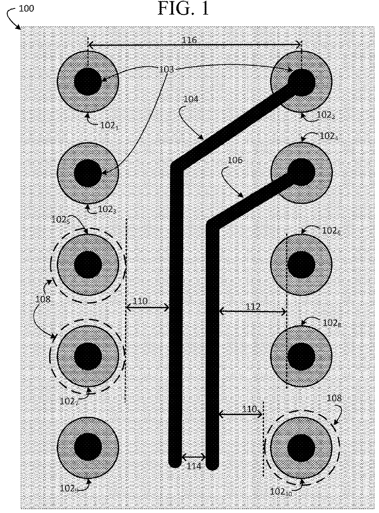
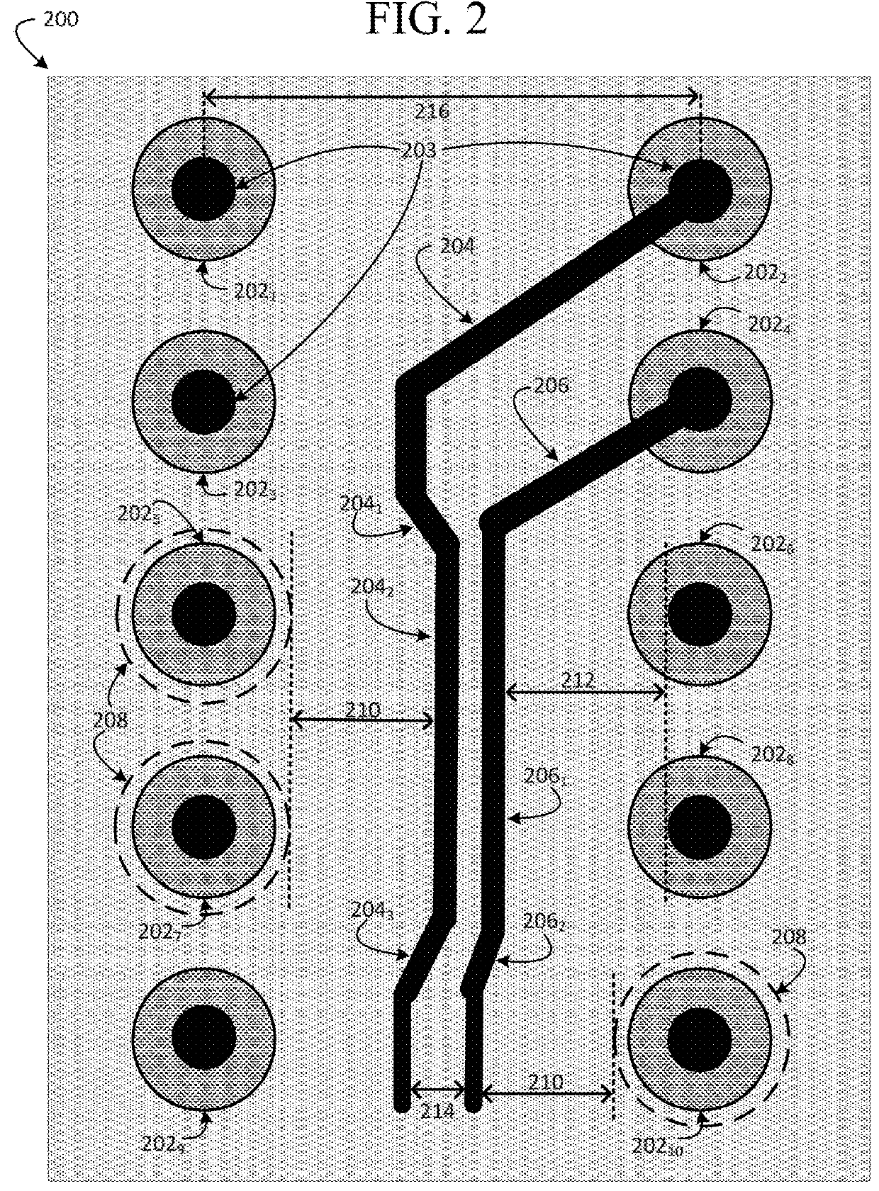
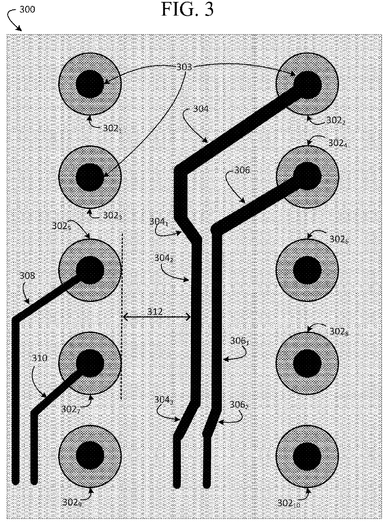
[0014]The present disclosure describes a technique for routing signal traces on printed circuit boards. In particular, the present disclosure relates to techniques for routing the traces to minimize the impact of rout...


PUM

PropertyMeasurementUnit
Lengthaaaaaaaaaa
Electrical conductoraaaaaaaaaa
Widthaaaaaaaaaa

Abstract

The subject technology provides a method and apparatus for performing dual track routing. A pair of signal traces is routed in between two rows of contacts and at least one of the signal traces is modified to satisfy a routing restriction. The modification of the signal trace includes three trace segments that deviate the signal trace away from the source of the routing restriction.

Description

CLAIM TO PRIORITY[0001]This application claims priority to U.S. provisional application No. 61 / 900,991, filed on Nov. 6, 2013, which is expressly incorporated by reference herein in its entirety.TECHNICAL FIELD[0002]The present technology relates in general to the field of printed circuit board layout, and in particular, to techniques for routing signals to and from an array of contacts.BACKGROUND[0003]Electronic systems used for computing and networking applications continue to evolve and increase in complexity. Routing the signals on a densely populated printed circuit board (PCB) or an integrated circuit (IC) used in these systems becomes extremely challenging due to restrictions associated with design and manufacturing constraints. For example, the evolution of ball-grid array (BGA) packaging to smaller pitch sizes presents unique challenges when fanning out signals. Design optimization is often balanced with the increased costs that accompany advanced manufacturing techniques.B...

Claims


Application Information

Patent Timeline
IPC IPC(8): H05K1/11H05K1/02G06F17/50
CPCG06F17/5077H05K1/0296H05K1/115G06F2217/06G06F2217/82H05K2201/09236H05K2201/09227H05K7/20H05K7/20009H05K7/20545H05K7/20709H05K7/20127H01R13/62994G06F30/394G06F2111/04G06F2119/10Y10T29/49156
Inventor SHEN, LINXIONG, YONGMINGMAHMOOD, SHAHBAZDE NICOLO, MAURILIO
Owner CISCO TECH INC
Why Eureka
Try Eureka