Echelle grating dense wavelength division multiplexer/demultiplexer

a technology of dense wavelength division and echelle grating, applied in the field of optical communication, can solve the problems of ineffective burying of additional fibers, rapid consumption of data transmission capacity, and exponential growth of data transmission volume of optical fibers

Inactive Publication Date: 2008-04-29
ONPOINT TECHNOLOGIES LLC
View PDF71 Cites 9 Cited by
  • Summary
  • Abstract
  • Description
  • Claims
  • Application Information

AI Technical Summary

Benefits of technology

[0006]In order to meet the requirements of DWDM, multiplexers and demultiplexers require certain inherent features. First, they must be able to provide for a high angular dispersion of closely spaced channels so that individual channels can be separated over relatively short distances sufficiently to couple with a linear array of outputs such as output fibers. Furthermore, the multiplexer / demultiplexer must be able to accommodate channels over a free spectral range commensurate with fiber optic communications bandwidth. Moreover, the devices must provide high resolution to minimize cross talk and must further be highly efficient to minimize signal loss. The ideal device would also be small, durable, thermally stable, inexpensive and scalable.

Problems solved by technology

The volume of data being transmitted by optical fibers is growing exponentially and the capacity for data transmission is rapidly being consumed.
Burying additional fibers is not cost effective.
Increasing the optical transmission rate is limited by the speed and economy of electronics surrounding the system as well as chromatic dispersion in the fibers.
Array waveguides suffer from the disadvantages of being expensive to design and manufacture, unable to provide high channel densities over broad wavelengths necessary for DWDM, thermal sensitivity and a lack of scalability and polarization dependent and high insertion losses.
However, the channel spacing of these devices, on the order of 0.8 or 1.6 nanometers (nm), limits the number of wavelengths that can be coupled into or out of a fibers.
Further, these devices present significant issues of optical loss, cross talk, alignment difficulties and thermal sensitivity.
This device has limited channel separation capacity and requires a tilt mechanism that can be difficult to control and is unreliable.
However, the device taught by Dueck fails to address the need to provide many channels for DWDM, high efficiency and a short focal length to provide a compact device.
Lundgren also fails to teach a DWDM device capable of accommodating high channel density and providing a high angular dispersion of channels so as to minimize focal length and apparatus size.
However, none of these systems provide the combination of beneficial attributes necessary to meet the growing needs for DWDM.

Method used


Image

  • Echelle grating dense wavelength division multiplexer/demultiplexer
  • Echelle grating dense wavelength division multiplexer/demultiplexer
  • Echelle grating dense wavelength division multiplexer/demultiplexer

Examples


embodiment 60

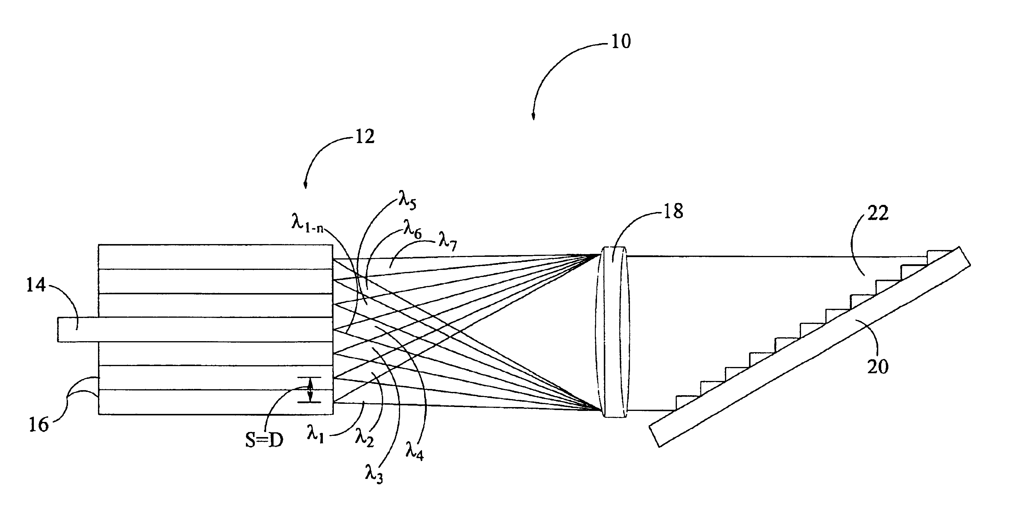
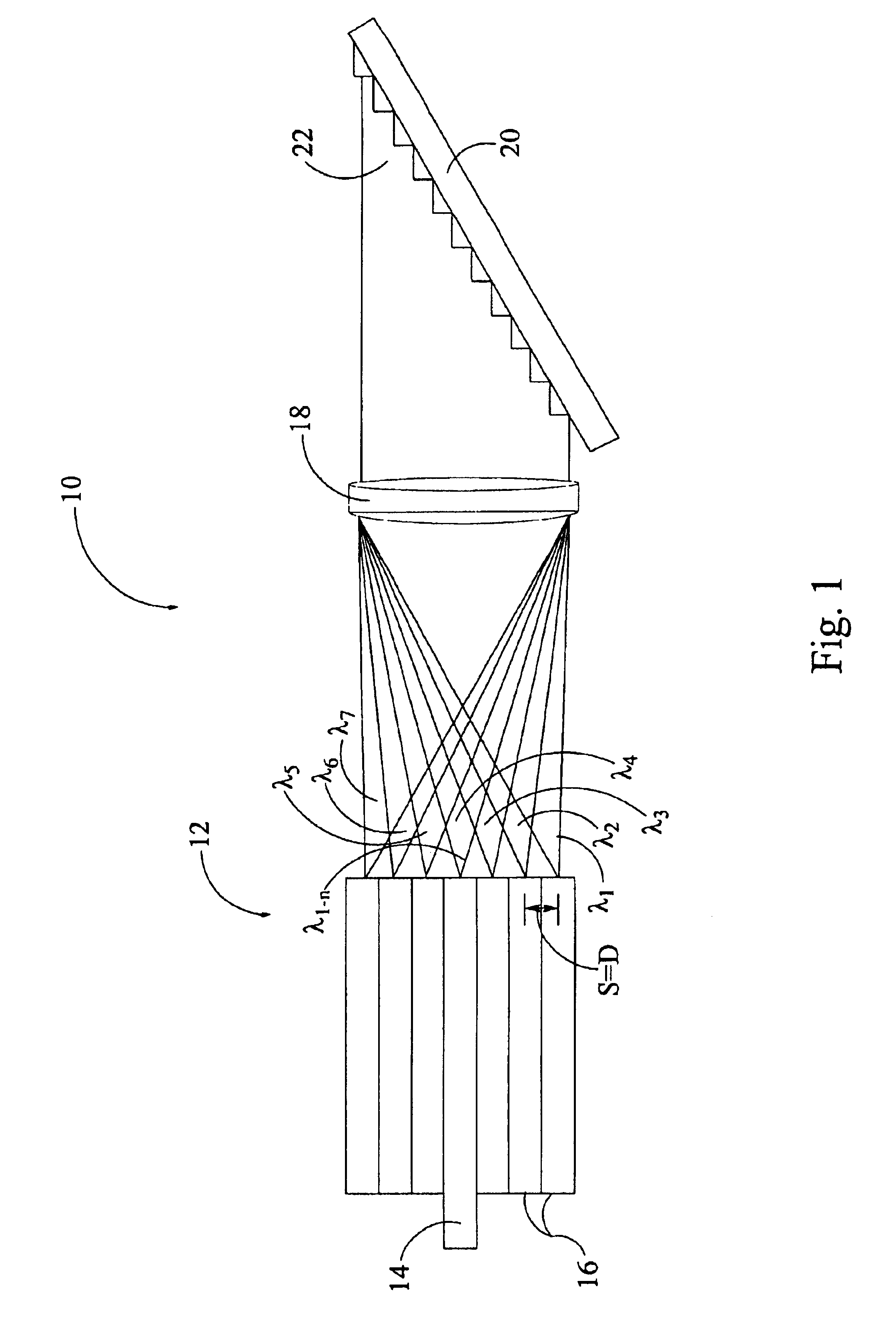
[0138]A second alternate embodiment 60 is illustrated in FIG. 8 which is a schematic representation of an echelle grating multiplexer / demultiplexer using a prism in combination with front surface optical mirrors. In this embodiment, light from a single mode input fiber 62 is directed off a collimating / focusing mirror 64 and the collimated beam 66 is directed through prism 68. The prism 68 provides for wavelength dispersion in a horizontal direction as indicated by the beams 70. These horizontally dispersed beams 70 are directed off the echelle grating 72 which in turn diffracts the beams 70 in an orthogonal dimension and directs these diffracted beams off the front surface of the concave collimating / focusing mirror 74. A two dimensional output fiber array 76 receives the focused beams from the collimating / focusing mirror 74. The use of the prism 68 in combination with the echelle grating 72 provides a two dimensional array of wavelength dispersion and may therefore facilitate detect...

embodiment 100

[0140]FIG. 10 is a fourth alternate embodiment 100 using an off-axis parabolic mirror as the collimating / focusing optic. In this embodiment, multiplexed light from the input fiber 102 is directed off the front surface of an off-axis parabolic mirror 104 which in turn directs a collimated beam of light 106 off the surface of an echelle grating 108. The multiplexed light is reflected off the surface of the echelle grating 108 back to the surface of the off-axis parabolic mirror 104 and dispersed to respective output fibers 106. In this embodiment, the echelle grating is in near-littrow configuration, thereby directing light back to the output fibers 106.

[0141]A fifth alternate embodiment illustrated in FIG. 11 uses a concave echelle grating 107 configured to be the optic which collimates and focuses the incoming beam. This embodiment eliminates the need for the collimating / focusing lenses or concave mirrors of alternate embodiments one-four.

[0142]Various modifications can be provided ...


PUM


Abstract

An apparatus for use in optical communication systems to multiplex / demultiplex an optical signal consisting of an optical channel(s) of distinct wavelength(s) having a select channel spacing within a select wavelength range. The apparatus includes a plurality of optical waveguides aligned generally along the same optical axis with each having a propagating end. At least two of the optical waveguides each propagate a distinct multiplexed optical signal comprising a plurality of channels, with the multiplexed optical waveguides being arranged in a multiplexed linear array. The others of the optical waveguides are single channel waveguides arranged in a two dimensional array with linear rows perpendicular to the multiplex linear array and with each linear row corresponding to a multiplex optical waveguide. A reflective echelle grating is optically coupled to the plurality of optical waveguides along the optical axis and receives an optical signal emitted from at least one of the optical waveguides and detracts the optical signal(s) to at least one other of the optical waveguide(s).

Description

RELATED APPLICATIONS[0001]This application is a reissue application of U.S. Pat. No. 6,647,182, issued Nov. 11, 2003, entitled “Echelle Grating Dense Wavelength Division Multiplexer / Demultiplexer,” which is a continuation-in-part application of U.S. patent application Ser. No. 09 / 628,774 now U.S. Pat. No. 6,415,080, filed Jul. 29, 2000, entitled, “Echelle Grating Dense Wavelength Division Multiplexer / Demultiplexer,” which claims priority from U.S. Provisional Patent Application Serial No. 60 / 209,018, filed Jun. 1, 2000, entitled “Lens-coupled Wavelength Division (De)multiplexing System Utilizing an Echelle Grating;” No. 60 / 152,218, filed Sep. 3, 1999, entitled “Method and Apparatus for Dense Wavelength Multiplexing and De-multiplexing Fiber Optic Signals Using an Echelle Grating Spectrograph;” No. 60 / 172,843, filed Dec. 20, 1999, entitled “Improved Method and Apparatus for Dense Wavelength Multiplexing and De-multiplexing Fiber Optic Signals Using an Echelle Grating Spectrograph;” a...

Claims


Application Information

Patent Timeline
Patent Type & Authority Patents(United States)
IPC IPC(8): G02B6/34G02B5/18G02B6/293
CPCG02B5/1861G02B6/29308G02B6/2931G02B6/29361G02B6/29373G02B6/2938
Inventor SAPPEY, ANDREW D.MURPHY, GERRY
Owner ONPOINT TECHNOLOGIES LLC
Why Eureka
Try Eureka