Respiratory gas flow sensor with sampling port

a gas flow sensor and sampling port technology, applied in the field of respiratory gas flow sensor with sampling port, can solve the problems of reducing the accuracy of volume flow measurement, inhibiting the effective emptying of the lung, and actual increase in blood carbon dioxide, so as to reduce dead space and weight, eliminate rogue leak measurement, and ensure volume flow measurement accuracy

Active Publication Date: 2018-06-19
EUROPLAZ TECH
View PDF6 Cites 2 Cited by
  • Summary
  • Abstract
  • Description
  • Claims
  • Application Information

AI Technical Summary

Benefits of technology

[0005]The present invention is an improved bi-directional constant temperature anemometry flow sensor, incorporating a gas sampling port arrangement which aims to assure volume flow measurement accuracy and eliminate rogue leak measurement. The device combines the two measuring functions into a single component for reduced deadspace and weight. The new arrangement of the gas sampling port is optimised to minimise turbulence and space prior to the sampling gas diversion point.
[0011]The distance between the orifice (or an opening in the position at which the gas is drawn from the flow path if that is remote from the orifice) and the anemometer sensor is important and is preferably within the range of 3-10 mm. This distance is usually measured (parallel to the flow path) from the edge of the orifice / opening nearest the sensor to the nearest part if the sensor. If the senor comprises one or more wire arranged perpendicularly across the flow path the distance may be measured from the wire nearest the orifice. The orifice or opening leading to the orifice may be shaped to minimise turbulence in the flow past it.
[0012]The flow path may ideally be defined by a substantially straight passageway. This can help to minimises turbulence and improve flow characteristics. The passageway may be tubular and usually is of a generally circular cross section, although it may have a different cross sectional shape.
[0014]The cross-sectional area of the flow path may be minimized to the smallest effective size according to the patient volume flow rate. This also reduces the deadspace volume.
[0015]Preferably a mesh is located across the flow path adjacent the first end and / or second end. One or more mesh may be provided across both ends and a mesh may comprise one or more overlaid layers mesh material. The mesh, or like component, helps to promote laminar flow and to protect the delicate sensor wires.

Problems solved by technology

In addition to causing under-measurement of the indicator for blood carbon dioxide, the deadspace may also result in an actual increase in blood carbon dioxide, by detracting from the amount of fresh gas exchange and causing rebreathing of previously exhaled gas.
However, this has effect of simultaneously increasing the gas flow resistance and inhibiting the effective emptying of the lung.
A further problem can exist caused by the diversion of gas flow for sampling as this can reduce accuracy in the volume flow measurement.
Modern ventilators would register such loss as a leak at the patient interface.
However, the leak effect is a further level of complexity for the clinician to consider, and thereby introduces a risk of sub-optimal ventilator settings.
Accidental over-distension (by too large a volume) may cause irreparable lung tissue damage.
Such calculations are potentially unreliable when using leak compensated volume estimation.

Method used


Image

  • Respiratory gas flow sensor with sampling port
  • Respiratory gas flow sensor with sampling port
  • Respiratory gas flow sensor with sampling port

Examples


third embodiment

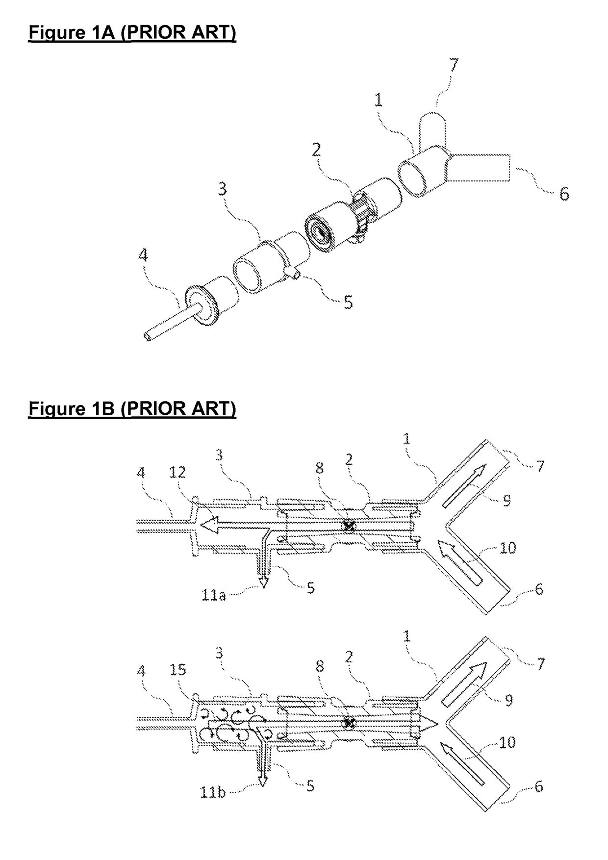
[0036]FIG. 2A illustrates a third embodiment with the same parts as shown in FIG. 1A; but where the gas sampling adapter 3 is inserted between the flow sensor 2 and the patient circuit manifold 1. This configuration eliminates the tidal volume flow measurement error and the rogue leak measurement aspects. The cross-sectional views in FIG. 2B shows how the gas sampling port 5 is now situated in a space within which significant gas mixing occurs, due to the expansion in the exhaled gas flow 15 and the collision with the continuous fresh gas flow 10 from the patient circuit. This configuration causes a more severe deterioration in the concentration measurement aspect.

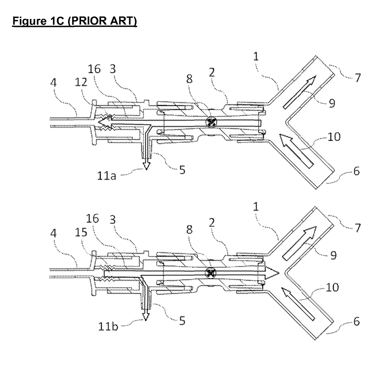
[0037]FIG. 3A illustrates a fourth version of the prior art in which a flow sensor 2 integrating a gas sampling port 5, in an arrangement that is substantially equivalent to a prior art device marketed by Corscience GmbH & Co, Germany. The gas sampling port 5 is arranged centrally and symmetrically to the constant temperat...

first embodiment

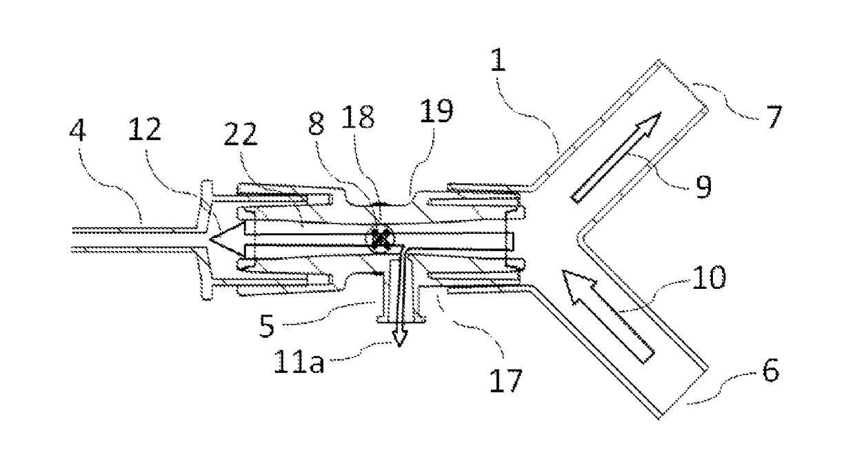
[0038]FIG. 4 shows an arrangement where combined flow sensor 19 of the present invention is inserted between the patient endotracheal tube 4 and the patient circuit manifold 1. A gas sampling port 5 in the flow sensor 19 is arranged asymmetrically offset upstream from the flow transducer 8.

[0039]FIG. 5 is a cross-sectional view illustrating the present invention flow sensor 19 connected to the endotracheal tube 4 and patient circuit manifold 1. A sampling gas portion 11a is diverted from the inhaled gas flow 12 prior to reaching the flow transducer 8. FIG. 5 also shows how a sampling gas portion 11b is diverted from the exhaled gas flow 15 after flowing across the flow transducer 8. Subject to the important dimensions described under FIG. 6, this flow sensor 2 arrangement eliminates measurement errors in both inhaled and exhaled tidal volumes, and therefore does not produce any rogue leak measurement. The bi-directional flow transducer 8 part of the design is based on two constant t...


PUM


Abstract

The accurate measurement of inspired and expired gas volume flow and gas composition are important in respiratory therapy. The invention provides a gas flow sensor for a ventilator comprising: a flow path extending between a first end that connects to a supply of gas and a second end that couples to a patient airway interface; and a constant temperature anemometer sensor arranged within the flow path between those ends. It further comprises a sampling port that may be coupled to a gas analyser device; and an orifice which is in fluid communication with the flow path and the sampling port so that, in use, gas may be drawn from the flow path for analysis, the gas being drawn from the flow path at a position located between the anemometer sensor and the first end.

Description

FIELD OF THE INVENTION[0001]The present invention relates to a component for use in medical artificial ventilation. The combined component includes a flow sensor for the measurement of the volume of gas flow and a port for extraction of sampling gas for routing to a concentration measurement device.BACKGROUND OF THE INVENTION[0002]For present purpose “patient circuit” means an open or re-circulating conduit for transporting respiratory gas between a ventilator and a human or animal patient. “Tidal volume” is the volume of air inhaled and exhaled at each breath. “Deadspace” is a volumetric space in the flow sensor and associated tube connectors from which gas does not reach the patient's alveoli during inhalation and / or which buffers carbon dioxide rich gas from reaching the exhaust channel during exhalation.[0003]Systems for measuring the gas volume flow and gas composition in respiratory therapy are well known. An example of a constant temperature anemometry flow sensor is describe...

Claims


Application Information

Patent Timeline
Patent Type & Authority Patents(United States)
IPC IPC(8): A61B5/08A61B5/087A61M16/08A61B5/097A61M16/14A61M16/12A61M16/00
CPCA61M16/085A61B5/0878A61B5/097A61M16/0003A61M16/0816A61M16/0841A61M16/12A61M16/14A61M16/0833A61M2206/11A61M2016/0033A61M2016/0036A61B5/083A61M2016/003
Inventor SANSOM, STEVEJENSEN, FREDE
Owner EUROPLAZ TECH
Why Eureka
Try Eureka