Tapping atomic force microscope with phase or frequency detection

Inactive Publication Date: 2000-01-11
BRUKER NANO INC
View PDF53 Cites 70 Cited by
  • Summary
  • Abstract
  • Description
  • Claims
  • Application Information

AI Technical Summary

Benefits of technology

Accordingly, one object of this invention is to provide a novel AFM that does not produce shea

Problems solved by technology

However, for samples that are very soft or interact strongly with the tip, such as photoresist, some polymers, silicon oxides, many biological samples, and others, the contact mode has drawbacks.
The lateral shearing forces may make the measurement difficult and for soft samples may damage the sample.
Further, a stick-slip motion may cause poor resolution and distorted images.
However for many samples and applications, immersion in liquid is not of much use.
Operating in liquid requires a fluid cell and increases the complexity of using the AFM, and for industrial samples such as photoresist and silicon wafers, immersion is simply not practical.
This limitation as will be shown limits the usefulness of the non-contact method.
Although developed at essentially the same time as the contact AFM, the non-contact AFM has rarely been used outside the research environment due to problems associated with the above constraints.
These operating conditions make the possibility very likely of the tip becoming trapped in the surface fluid layer described by Hansma et al.
As can be seen from

Method used


Image

  • Tapping atomic force microscope with phase or frequency detection
  • Tapping atomic force microscope with phase or frequency detection
  • Tapping atomic force microscope with phase or frequency detection

Examples


Embodiment Construction

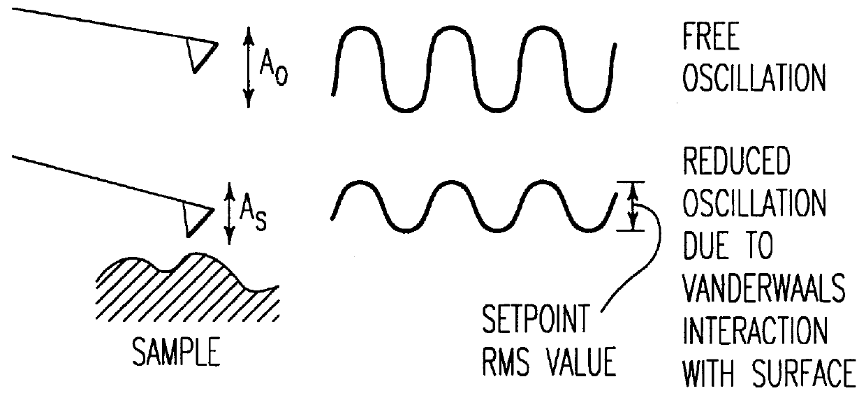
The present invention utilizes the inventors' discovery that if the probe is oscillated at or near one of the resonant frequencies of the lever, that in fact the probe tip has much less of a tendency to stick to the surface because a resonant system tends to remain in stable oscillation even if some damping exists. Thus the preferred embodiment of the present invention utilizes a resonant oscillation of the cantilever at sufficient oscillation amplitude to achieve the advantages described above without the probe becoming stuck to the surface. This preferred embodiment also provides many of the benefits of the non-contact AFM as described above.

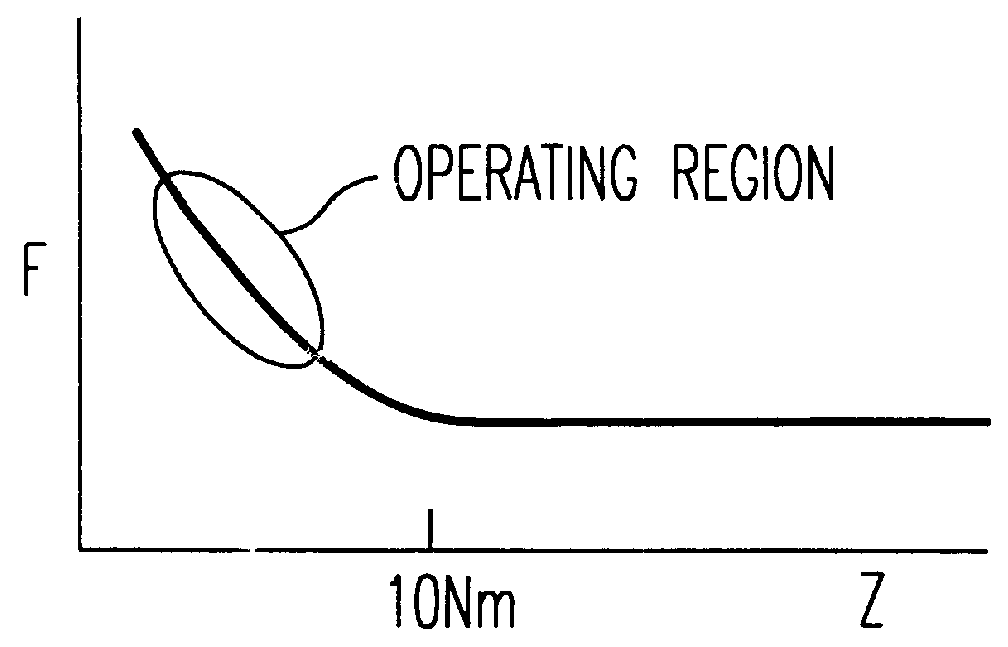
Existing development of AFM's using oscillation of the probes has been directed at avoiding surface contact, as described above, and as such is limited in practicality despite the potential advantages of the technique. For applications where the non-contact mode is desired, the inventors have found that the amplitude-distance curve of FIG. 6 c...


PUM


Abstract

An atomic force microscope in which a probe tip is oscillated at a resonant frequency and at amplitude setpoint and scanned across the surface of a sample, which may include an adsorbed water layer on its surface, at constant amplitude in intermittent contact with the sample and changes in phase or in resonant frequency of the oscillating are measured to determine adhesion between the probe tip and the sample. The setpoint amplitude of oscillation of the probe is greater than 10 nm to assure that the energy in the lever arm is much higher than that lost in each cycle by striking the sample surface, thereby to avoid sticking of the probe tip to the sample surface. In one embodiment the probe tip is coated with an antibody or an antigen to locate corresponding antigens or antibodies on the sample as a function of detected variation in phase or frequency. In another embodiment, the frequency of oscillation of the probe tip is modulated and relative changes in phase of the oscillating probe tip observed in order to measure the damping of the oscillation due to the intermittent or constant tapping of the surface by the tip. In a further embodiment, the slope of the phase versus frequency curve is determined and outputted during translating of the oscillating probe. Force dependent sample characteristics are determined by obtaining data at different tapping amplitude setpoints and comparing the data obtained at the different tapping amplitude setpoints.

Description

BACKGROUND OF THE INVENTION1. Field of the InventionThis invention relates to an ultra-low force atomic force microscope, and particularly an improvement to the atomic force microscope described in related commonly owned U.S. patent application Ser. No. 08 / 147,571 and related U.S. Pat. Nos. 5,229,606 and 5,266,801.2. Discussion of the BackgroundAtomic Force Microscopes (AFM's) are extremely high resolution surface measuring instruments. Two types of AFM's have been made in the past, the contact mode (repulsive mode) AFM and the non-contact (attractive mode) AFM.The contact mode AFM is described in detail in U.S. Pat. No. 4,935,634 by Hansma et al, as shown in FIG. 2. This AFM operates by placing a sharp tip attached to a bendable cantilever directly on a surface and then scanning the surface laterally. The bending of the lever in response to surface height variations is monitored by a detection system. Typically, the height of the fixed end of the cantilever relative to the sample i...

Claims


Application Information

Patent Timeline
IPC IPC(8): G12B21/20G12B21/08G12B21/00G01Q60/24G01Q60/34
CPCB82Y35/00G01Q60/34
Inventor ELINGS, VIRGIL B.GURLEY, JOHN A.
Owner BRUKER NANO INC
Why Eureka
Try Eureka