Optical scanning head

a scanning head and optical technology, applied in the field of scanning systems, can solve the problem that the actual ccd bar code scanner does not provide the comfort of the laser scanner, and achieve the effect of improving the depth of field and the angular distan

Inactive Publication Date: 2000-01-25
SYMBOL TECH INC
View PDF23 Cites 337 Cited by
  • Summary
  • Abstract
  • Description
  • Claims
  • Application Information

AI Technical Summary

Benefits of technology

Due to the exterior transmission of the incident beam, the field and the depth of view are substantially independent of the width of the window or housing, because of the LEDs position, lenses and filter assembly mounted in the front of the dark room, between the top and the bottom region. Put another way, the angular distance and depth of field are considerably improved.

Problems solved by technology

The actual CCD bar code scanner does not provide the comfort of the laser scanner which allows to read the bar code symbols at the variable distance and greater than the window or housing width.

Method used


Image

  • Optical scanning head
  • Optical scanning head
  • Optical scanning head

Examples


Embodiment Construction

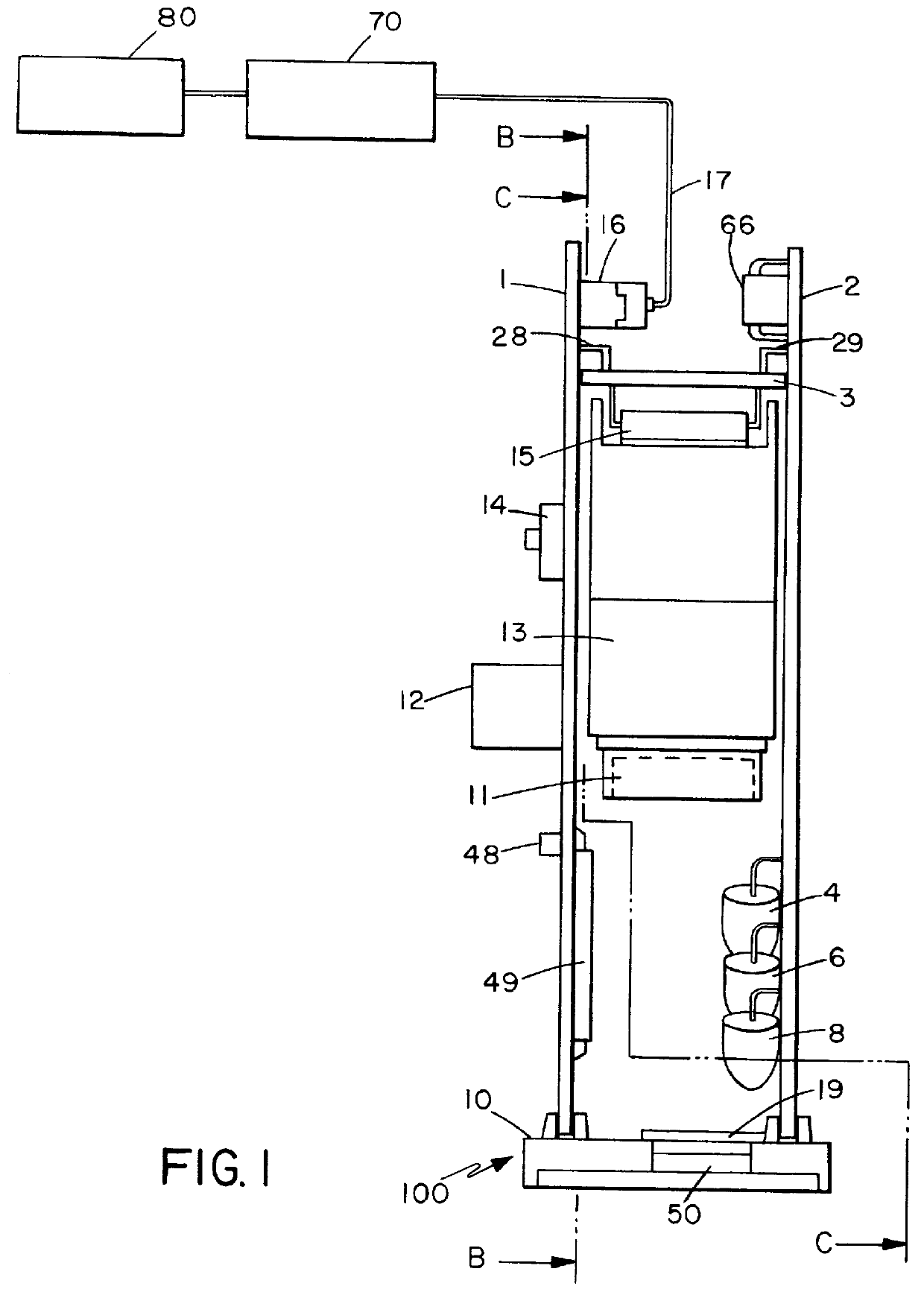
Referring now to FIGS. 1-7 of the drawings, reference numeral 100 generally identifies a scanning head, easy to use and to integrate in an enclosure or other products for reading, scanning and / or analyzing bar code symbols throughout thereof. The scanning head way include the decoder module which decodes a multiple-digit representation of the bar code symbols such as UPC, EAN, JAN, Code 39, Code 2 / 5I, Code 2 / 5, Code 128, Codabar, Plessey, etc.

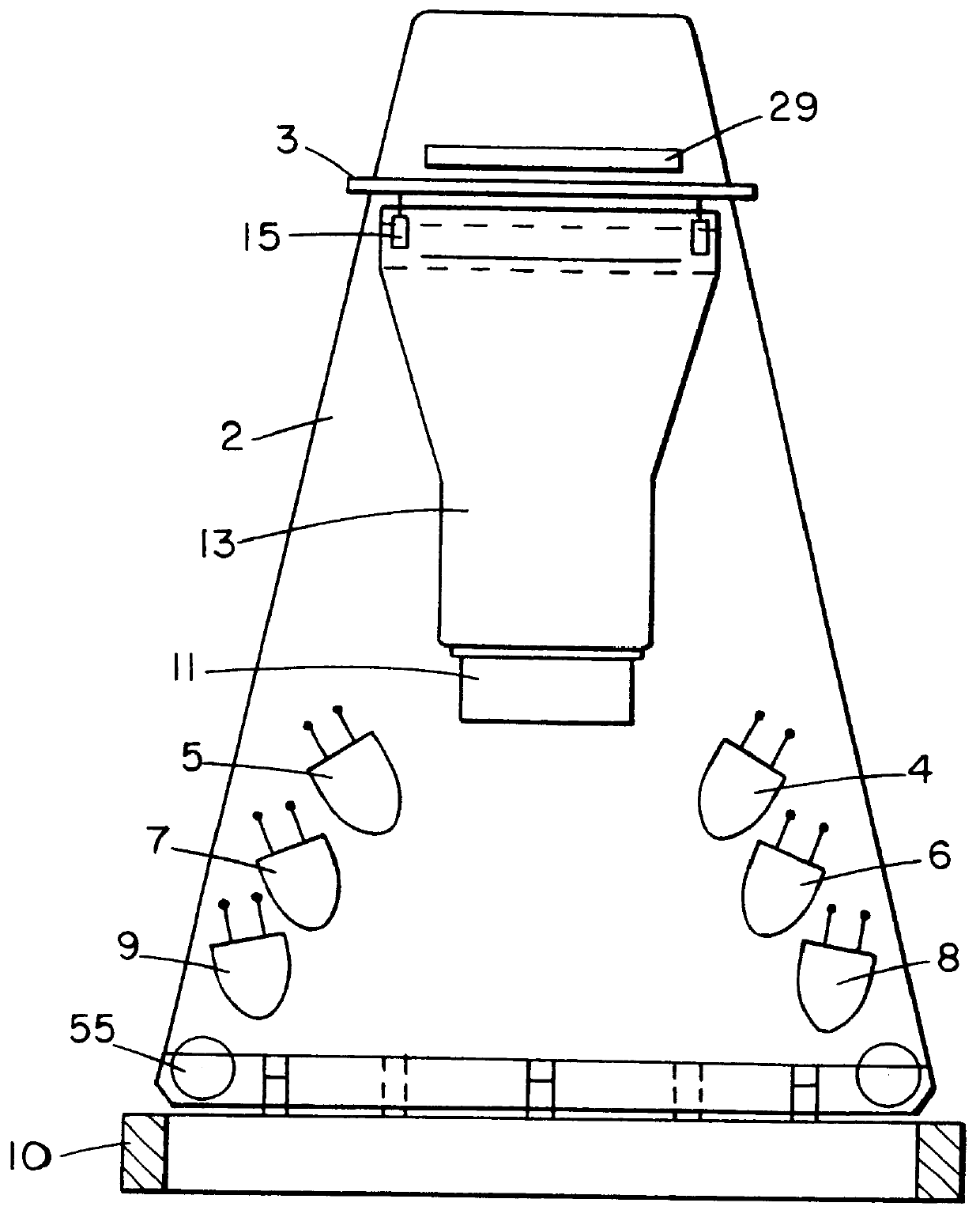
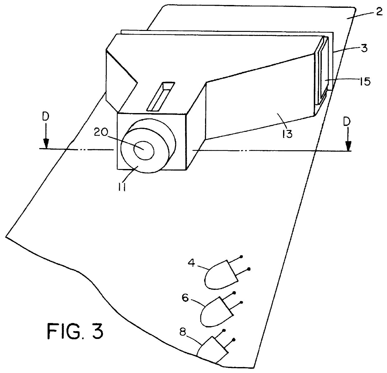
Referring to FIG. 1, the scanning head 100 includes generally a window portion 10 holding the printed board portion 1 and portion 2. The printed board portion 3 is mounted between portion 1 and 2, in the rear region of the scanning head 100. The portion 1 and 2 are spaced apart of each other by a predetermined height dimension.

A light source means, i.e., six LEDs 4-9. Three LEDs are soldered in different direction, on each side of the surface of portion 2, along the longitudinal axis and are operative for generating, each one, a fraction of the...


PUM

PropertyMeasurementUnit
wavelengthaaaaaaaaaa
widthaaaaaaaaaa
widthaaaaaaaaaa

Abstract

The [ornamental] design for a bar code Scanner using the Light Emitting Diode (LED), Optical Scanner assembly and Charge-Coupled Devices (CCD) capable of reading the barcode symbols at the variable distance, as shown and described. The optical passive elements for increasing the depth of field and method of fabricating the scanning head by mass-production techniques are also disclosed.

Description

FIELD OF THE INVENTIONThe present invention generally relates to scanning system for reading and / or analyzing bar code symbols, and more particularly, to a light-weight, easy to integrate, single windowed, bar code scanning head supportable entirely by a user, system integrator and manufacturer (who wishes to integrate the scanning head in their own devices as bar code reading device) throughout the reading of the symbols.BACKGROUND OF THE INVENTIONMany industries, including the assembly processing, grocery and food processing industry, have designated their products with a bar code symbol consisting of a series of lines and spaces of varying widths. Different bar code readers and laser scanning systems have been developed to decode the symbol pattern to a multiple digit representation for inventory, production-tracking and check-out purposes.Modern miniature laser scanners using the laser diode, have recently been proposed to provide a portable and integrable laser scanning head fo...

Claims


Application Information

Patent Timeline
Patent Type & Authority Patents(United States)
IPC IPC(8): G03F7/20G06K7/10
CPCG03F7/705G06K7/10722G06K7/10732G06K7/10742G06K7/10811G06K7/1092
Inventor ROUSTAEI, ALEXANDER R.
Owner SYMBOL TECH INC
Why Eureka
Try Eureka