Soil sampling system with sample container rigidly coupled to drive casing

a sampling system and drive casing technology, applied in the direction of sealing/packing, instruments, borehole/well accessories, etc., can solve the problems of contaminated soils, serious environmental and health problems, and difficulty in identifying and treating contaminated soils, so as to improve the speed and efficiency of the system, convenient movement, reliable and effective sampling

Inactive Publication Date: 2001-02-27
PRECISION SAMPLING
View PDF9 Cites 10 Cited by
  • Summary
  • Abstract
  • Description
  • Claims
  • Application Information

AI Technical Summary

Benefits of technology

Removal of the sample from the soil is much easier than in the prior art. Because the borehole is sealed off by the drive casing, there is no soil-skin friction to overcome when retrieving the sample barrel. Removal of the sample barrel (containing the soil samples in the sample liners) is easier and quicker, improving the speed and efficiency of the system of the invention as compared to previous systems.
The rig driving the soil sampling system can be significantly more compact than is typical in the prior art. It can be mounted on a conventional skid loader, and thus can be conveniently moved into locations that would not accommodate a conventional drilling rig. The rig can be configured to slant drill and can even drill horizontally. The double-rod sampling system can thus sample under buildings or existing structures without the necessity of dismantling or destroying them. Thus, the invention provides for reliable and effective sampling of contaminated soils, even at sites where access is restricted.
In a method in accordance with the invention, a drive casing, sample barrel, and sample liners are driven simultaneously into the soil to essentially the same depth. Thus, all portions of the borehole are sealed off while the sample is obtained, preventing sample contamination from sloughed-off soil from higher levels. In addition, the sample barrel and liners can be removed and replaced while the drive casing stays in place.
The method of the invention of taking and retrieving samples facilitates the taking of continuous samples. The bottom sample depth attained by one round of sampling becomes the top sample depth of the next round of sampling. A continuous sample is thus obtained and even thin layers of contamination are retrieved, thus maximizing sampling reliability. These and other features and advantages of the present invention are apparent in the following description with reference to the drawings below.

Problems solved by technology

Contamination of soils is a major environmental concern.
Toxic compounds can remain in the soil for years, and can seep into groundwater, causing serious environmental and health problems.
Because contamination is often located many feet below the surface, identifying and treating contaminated soils can be problematic.
The discrete sampling of many previous systems, often taken at intervals of several feet, can miss areas of contamination and yield false negative results.
Furthermore, where contamination is encountered, the cuttings created by the typical augering system and brought to the ground surface, are also often contaminated, and must be disposed of as hazardous waste.
Such disposal is often difficult and very expensive, because the soil requires special handling and disposal.
Single-rod systems can often be driven by more compact drilling rigs, but they are associated with other problems.
In addition, because the borehole is not continuously cased off, contaminants from upper levels often slough off and contaminate lower levels, leading to false positive readings.
The drilling rig and winch in the typical prior art system can often harm the environment around the area to be tested.
A rig in place can disrupt traffic.
Landscaping around the area to be tested can be destroyed.
Providing access for the equipment can also be destructive, time-consuming, and expensive.

Method used


Image

  • Soil sampling system with sample container rigidly coupled to drive casing
  • Soil sampling system with sample container rigidly coupled to drive casing
  • Soil sampling system with sample container rigidly coupled to drive casing

Examples


Embodiment Construction

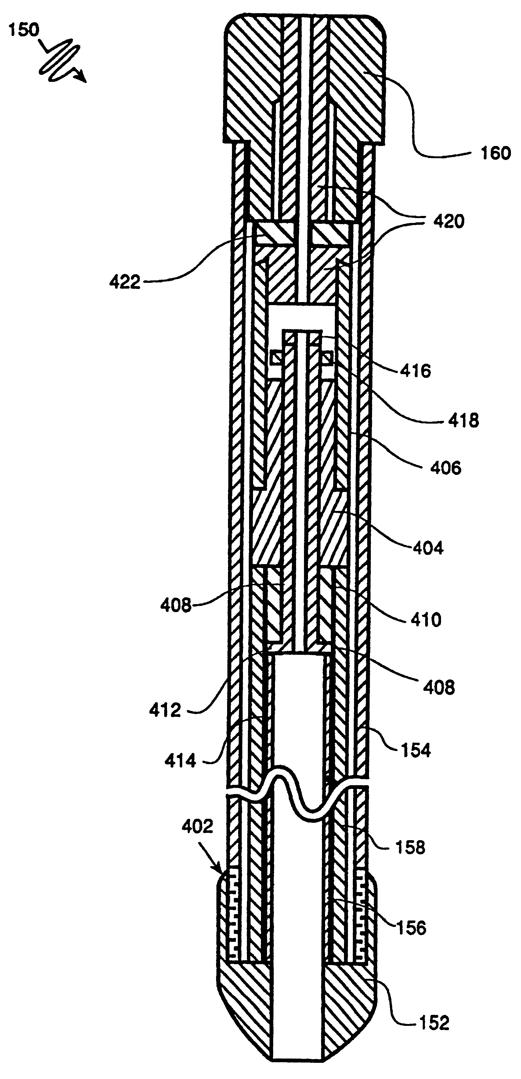
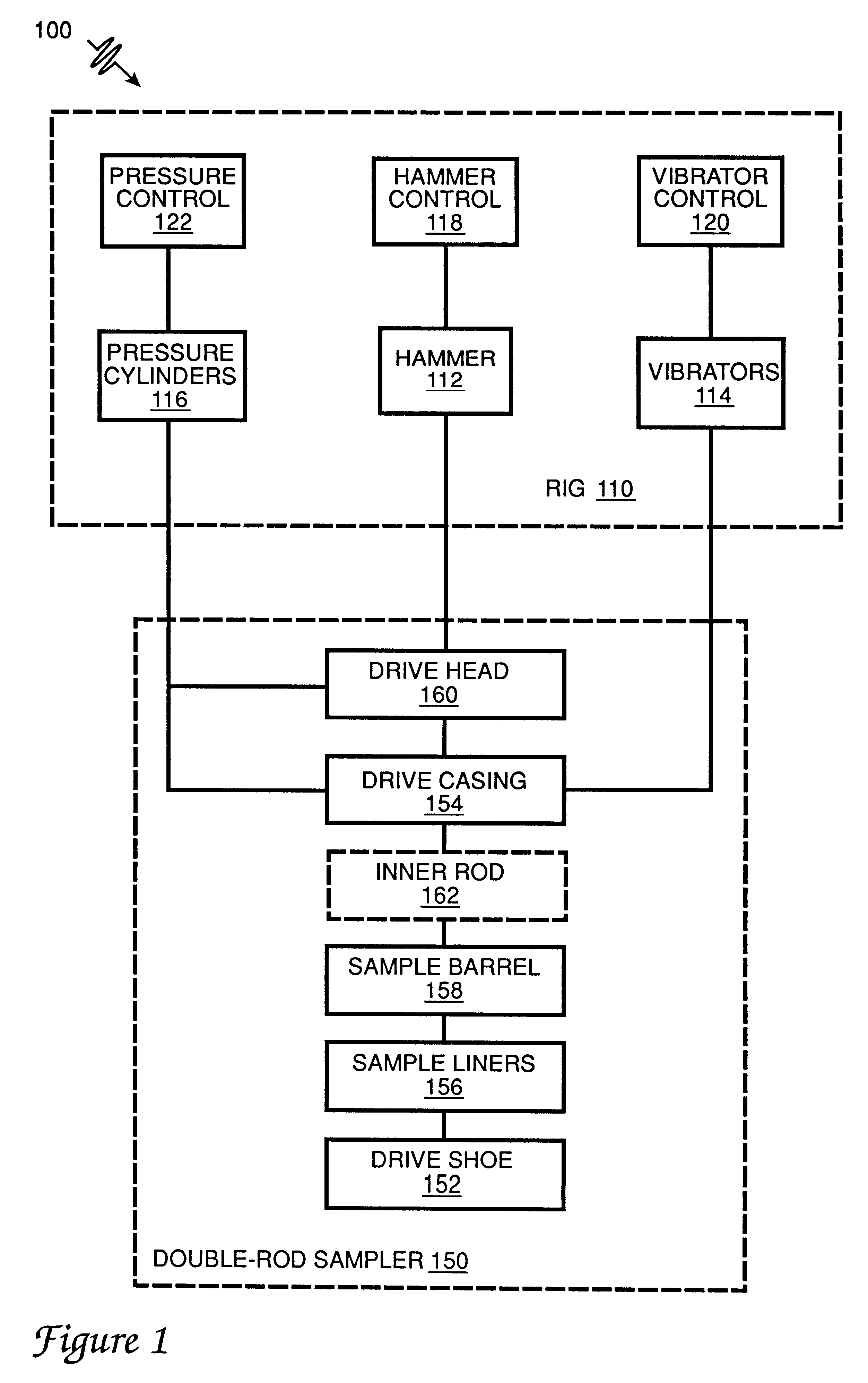
In accordance with the present invention, a double-rod soil sampling system 100 comprises a sampling rig 110 and a double-rod sampler 150, a shown in FIGS. 1 and 2. Sampling rig 110 includes three driving systems: a hydraulic hammer 112, hydraulic vibrators 114, and hydraulic pressure cylinders 116, shown in block diagram in FIG. 1. Respective drive controls include hammer controls 118 (including a hammer slide control that horizontally positions hammer 112 and a hammer pounding control the controls the pounding of hammer 112); a vibrator control 120; and a pressure control 122.

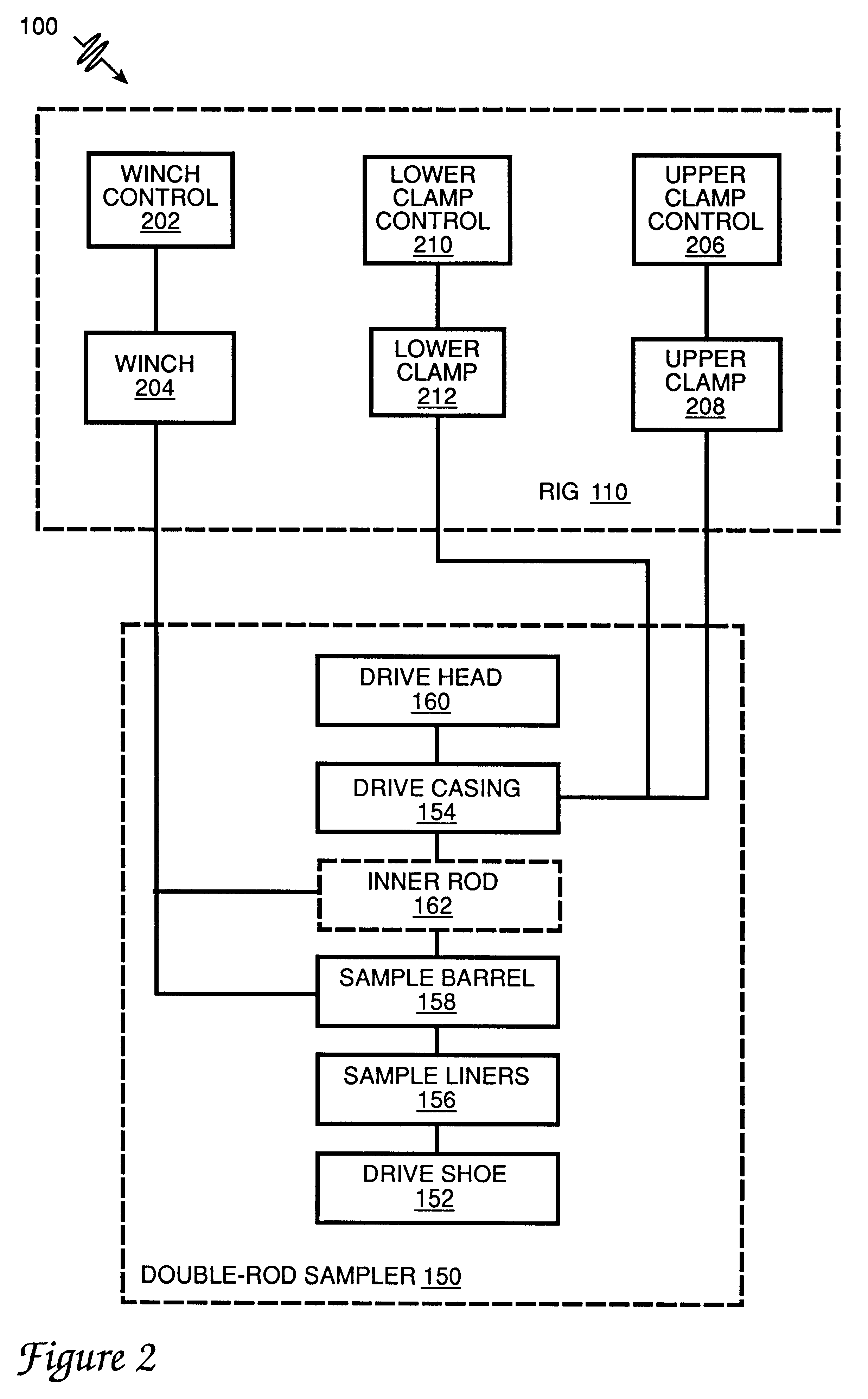
Sampling rig 110 also includes two retraction systems and their controls, as shown in block diagram in FIG. 2. A sample retrieval system includes a winch control 202 and a winch 204. A sampler retrieval system includes an upper clamp control 206, controlling upper clamp 208, and a lower clamp control 210, controlling lower clamp 212. The controls are mounted on the rig and control the respective driving and r...


PUM

PropertyMeasurementUnit
frequencyaaaaaaaaaa
pressureaaaaaaaaaa
anglesaaaaaaaaaa

Abstract

A soil sampling system includes a rig for driving a drive casing, a sample barrel, and sample liners simultaneously into soil to be sampled. The rig includes mechanisms for driving the casing, barrel, and lining in three modes: hydraulic hammer, continuous pressure, and vibration. The three drive mechanisms can be operated singly or in any combination. After the casing, barrel, and liners are advanced a selected depth into the soil, the barrel and liners are removed. The drive casing remains in the soil. New sample liners are put into the sample barrel, and an inner rod is attached to the sample barrel. The sample barrel is then replaced into the drive casing, and extensions are attached to the drive casing. The drive casing, including extensions, and the sample barrels, along with sample liners and inner rod, are driven further down into the soil. The rig also includes a winch that can be coupled to the inner rod or sample barrel so that the casing and/or barrel (including sample liners) can be retrieved from the drive casing. A clamp system allows the sampler to be hydraulically retracted from the ground when sampling is finished.

Description

BACKGROUND OF THE INVENTIONThe present invention relates to soil sampling systems and, more particularly, to hollow-tubed soil samplers. A major objective of the present invention is to provide for enhanced collection of soil samples for chemical or physical analysis.Contamination of soils is a major environmental concern. Toxic compounds can remain in the soil for years, and can seep into groundwater, causing serious environmental and health problems. Because contamination is often located many feet below the surface, identifying and treating contaminated soils can be problematic.In a typical system for sampling for soil contamination, soil samples are collected at discrete levels. A hollow-stem auger powered by a large motor drill rig is typically used. The drilling rig can weigh as much as 30 tons, and is typically mounted on a large truck. The auger is typically about 8" in diameter. The outside has a spiral flighting that aids travel through the soil and that removes the waste ...

Claims


Application Information

Patent Timeline
Patent Type & Authority Patents(United States)
IPC IPC(8): E21B33/127E21B25/00E21B25/02E21B33/12
CPCE21B25/02E21B33/127
Inventor CASEY, MICHAEL B.EINARSON, MURRAY D.
Owner PRECISION SAMPLING
Why Eureka
Try Eureka