Corrosion resistant PEM fuel cell

a fuel cell and corrosion resistance technology, applied in the direction of fuel cell details, fuel cells, electrochemical generators, etc., can solve the problems of difficult mechanical handling and processing of contact elements made therefrom, difficult to make very thin gas impervious plates, and quite fragile graphite, etc., to achieve low electrical resistivity and not easy to crack

Inactive Publication Date: 2001-07-17
GM GLOBAL TECH OPERATIONS LLC
View PDF9 Cites 70 Cited by
  • Summary
  • Abstract
  • Description
  • Claims
  • Application Information

AI Technical Summary

Problems solved by technology

However, graphite is quite fragile which makes it difficult to mechanically handle and process contact elements made therefrom.
Moreover, graphite is, quite porous making it virtually impossible to make very thin gas impervious plates.
The pores in graphite often lead to gas permeation under the fuel cell's operating pressure which could lead to the undesirable mixing of H.sub.2 and O.sub.2.
Finally, the electrical and thermal conductivity of graphite is quite low compared with light weight metals such as aluminum and titanium and their alloys.
Unfortunately, such light weight metals are either not corrosion resistant in the PEM fuel cell environment, and contact elements made therefrom deteriorate rapidly, or they form highly electronically resistive oxide films on their surface that increases the internal resistance of the fuel cell and reduces its performance.

Method used


Image

  • Corrosion resistant PEM fuel cell
  • Corrosion resistant PEM fuel cell
  • Corrosion resistant PEM fuel cell

Examples


Embodiment Construction

The invention will be better understood when considered in the light of the following detailed description thereof which is given hereafter in conjunction with the following drawings of which:

BRIEF DESCRIPTION OF THE DRAWINGS

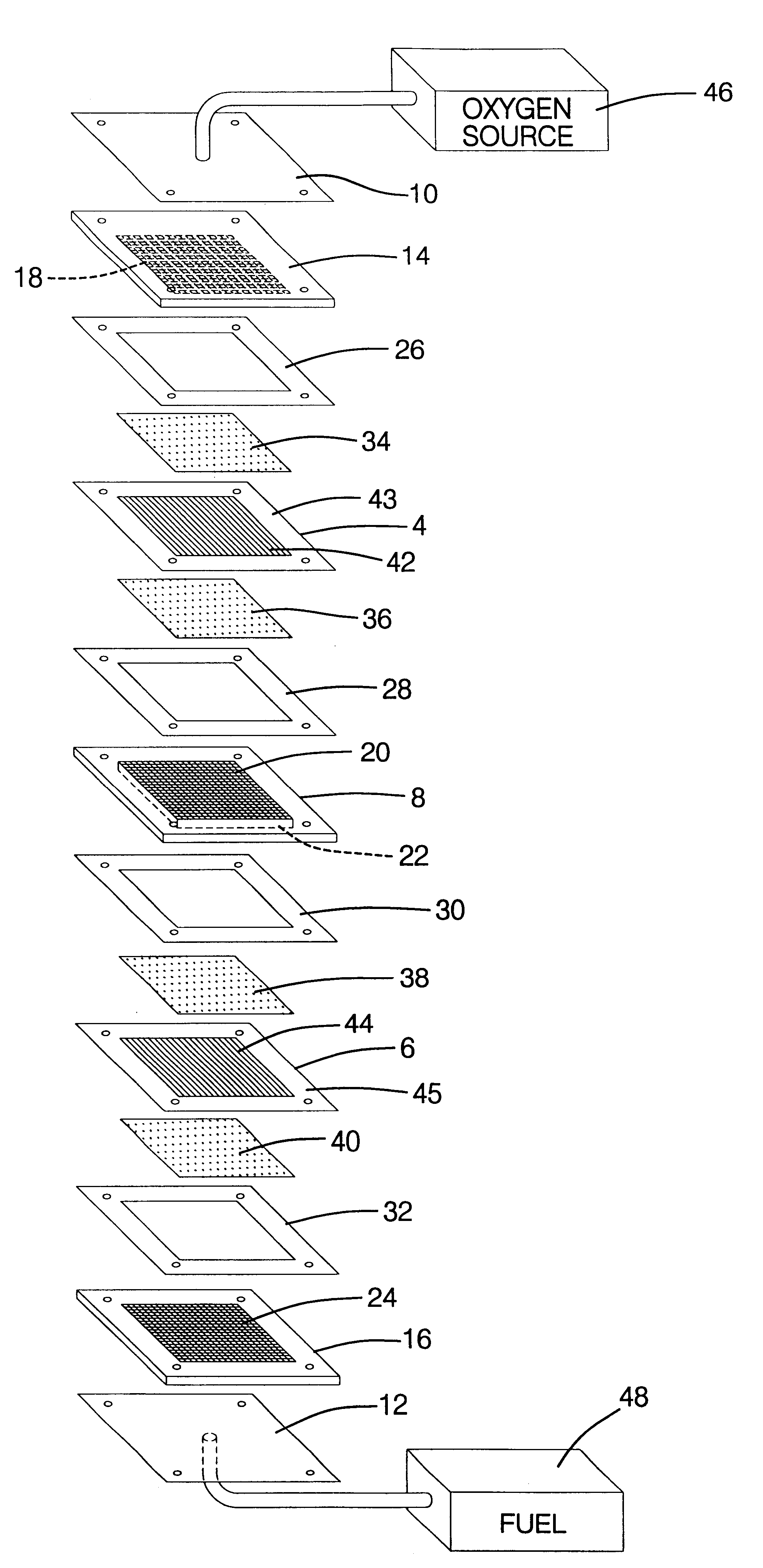
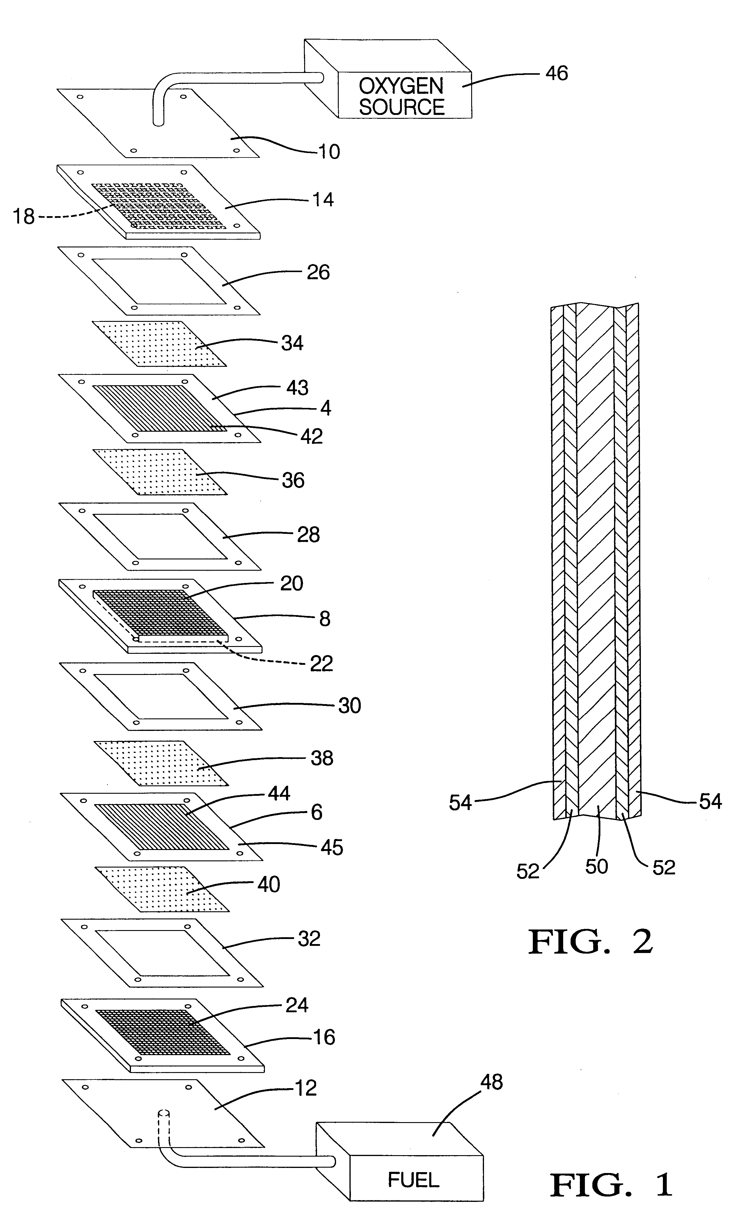
FIG. 1 is a schematic, isometric, exploded view of a bipolar PEM fuel cell;

FIG. 2 is sectioned view through the bipolar plate of FIG. 1;

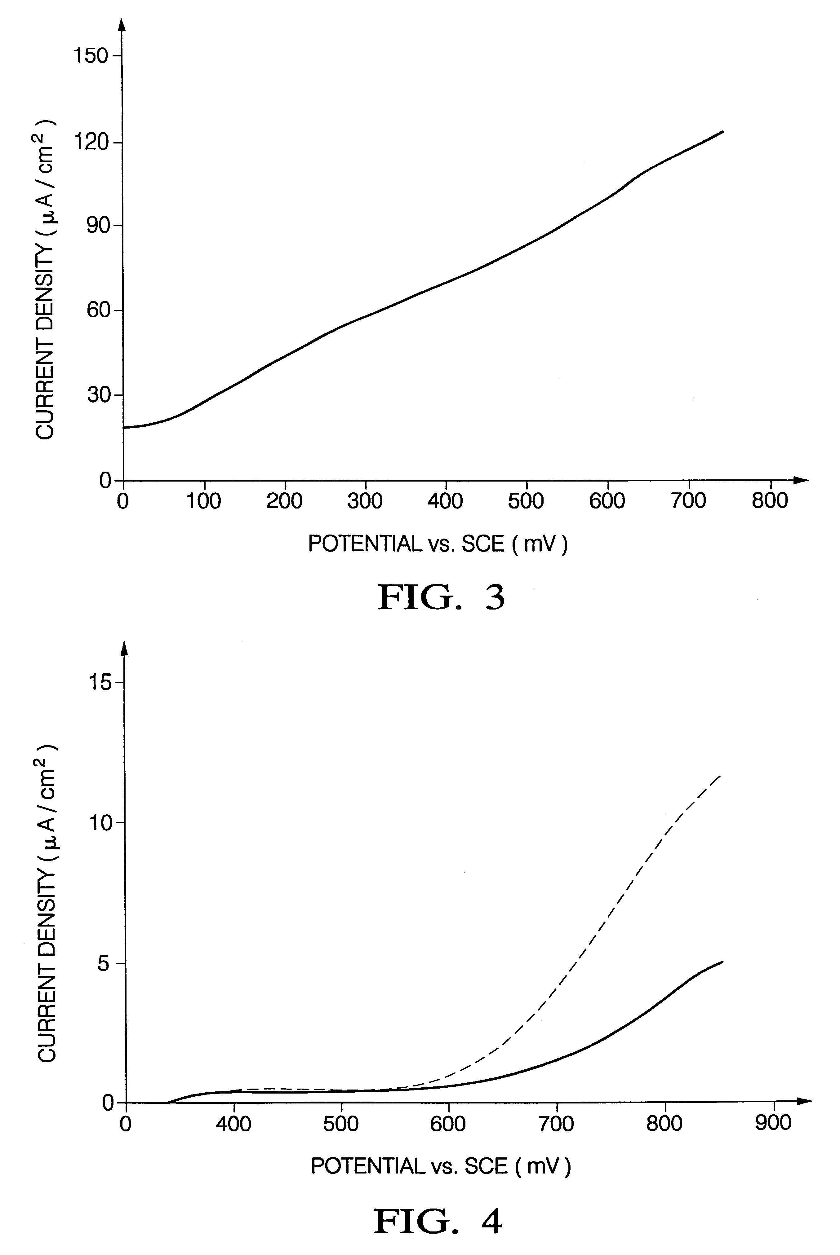
FIG. 3 is a potentiodynamic polarization curve of a bare aluminum 6061-T6 in a simulated fuel cell environment;

FIG. 4 are typical potentiodynamic polarization curves for aluminum coated with (a) just stainless steel, and (2) both stainless steel and TiN in a simulated fuel cell environment;

FIG. 5 is a current vs. time plot of a TiN / SS-coated aluminum substrate at a constant anodic polarization of 760 mV vs. SCE; and

FIG. 6 is a measured resistance plot for different lengths of "as-deposited"and " post corrosion testing " of a TiN film.

FIG. 1 depicts a two cell, bipolar PEM fuel cell having a pair of membrane-electrode-assemblies ...


PUM

PropertyMeasurementUnit
pHaaaaaaaaaa
pressureaaaaaaaaaa
pressureaaaaaaaaaa

Abstract

The present invention contemplates a PEM fuel cell having electrical contact elements (including bipolar plates / septums) comprising a titanium nitride coated light weight metal (e.g., Al or Ti) core, having a passivating, protective metal layer intermediate the core and the titanium nitride. The protective layer forms a barrier to further oxidation / corrosion when exposed to the fuel cell's operating environment. Stainless steels rich in CR, Ni, and Mo are particularly effective protective interlayers.

Description

This invention relates to PEM fuel cells and more particularly to corrosion-resistant electrical contact elements therefor.BACKGROUND OF THE INVENTIONFuel cells have been proposed as a power source for electric vehicles. One such fuel cell is the PEM (i.e., Proton Exchange Membrane) fuel cell as it has potentially high energy and low weight, both of which are highly desirable for mobile electric vehicles. PEM fuel cells are well known in the art, and include a so-called "membrane-electrode-assembly" comprising a thin, solid polymer membrane-electrolyte having an anode on one face of the membrane-electrolyte and a cathode on the opposite face of the membrane-electrolyte. The membrane-electrode-assembly is sandwiched between a pair of electrically conductive elements which serve as current collectors for the anode / cathode and often contain appropriate channels and openings therein for distributing the fuel cell's gaseous reactants (e.g., H.sub.2 & O.sub.2 / air)over the surfaces of the...

Claims


Application Information

Patent Timeline
Patent Type & Authority Patents(United States)
IPC IPC(8): H01M8/10H01M8/02
CPCH01M8/0206H01M8/0208H01M8/0215H01M8/0228H01M2300/0082Y02E60/50
Inventor LI, YANGMENG, WEN-JINSWATHIRAJAN, SWATHYHARRIS, STEPHEN JOELDOLL, GARY LYNN
Owner GM GLOBAL TECH OPERATIONS LLC
Why Eureka
Try Eureka