
Liquid crystal display element and micro-lens arrangement and a display using the same

a technology of liquid crystal display elements and micro-lens arrays, which is applied in the direction of color television details, identification means, instruments, etc., can solve the problems of reducing light utilization efficiency, difficult to increase light intensity, and large effect of light shielding portions, so as to improve the focusing characteristic of micro-lens arrays and smooth display. , the effect of increasing light utilization efficiency

Inactive Publication Date: 2003-07-08
HITACHT MAXELL LTD
View PDF29 Cites 4 Cited by
  • Summary
  • Abstract
  • Description
  • Claims
  • Application Information

AI Technical Summary

Benefits of technology

Accordingly, it is an object of the invention to solve the problems in the prior art and provide a liquid crystal display element capable of effectively using all the light incident to the liquid crystal display element, thus greatly improving the aperture ratio.
It is another object of the invention to provide a bright, compact and good-performance liquid crystal display using a liquid crystal display element and an illumination optical system which has a high light utilization efficiency for the light from a light source, a small number of parts such as lenses, is compact, and can further improve the effect of the liquid crystal display element of which the aperture ratio is greatly improved.
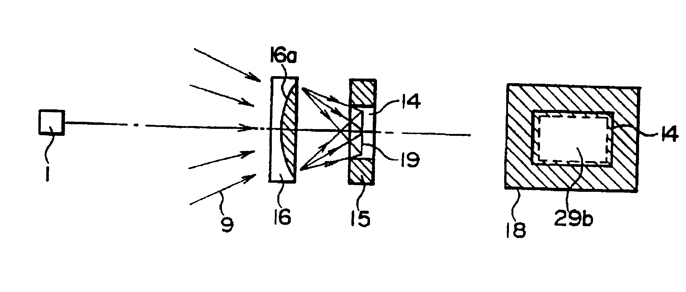
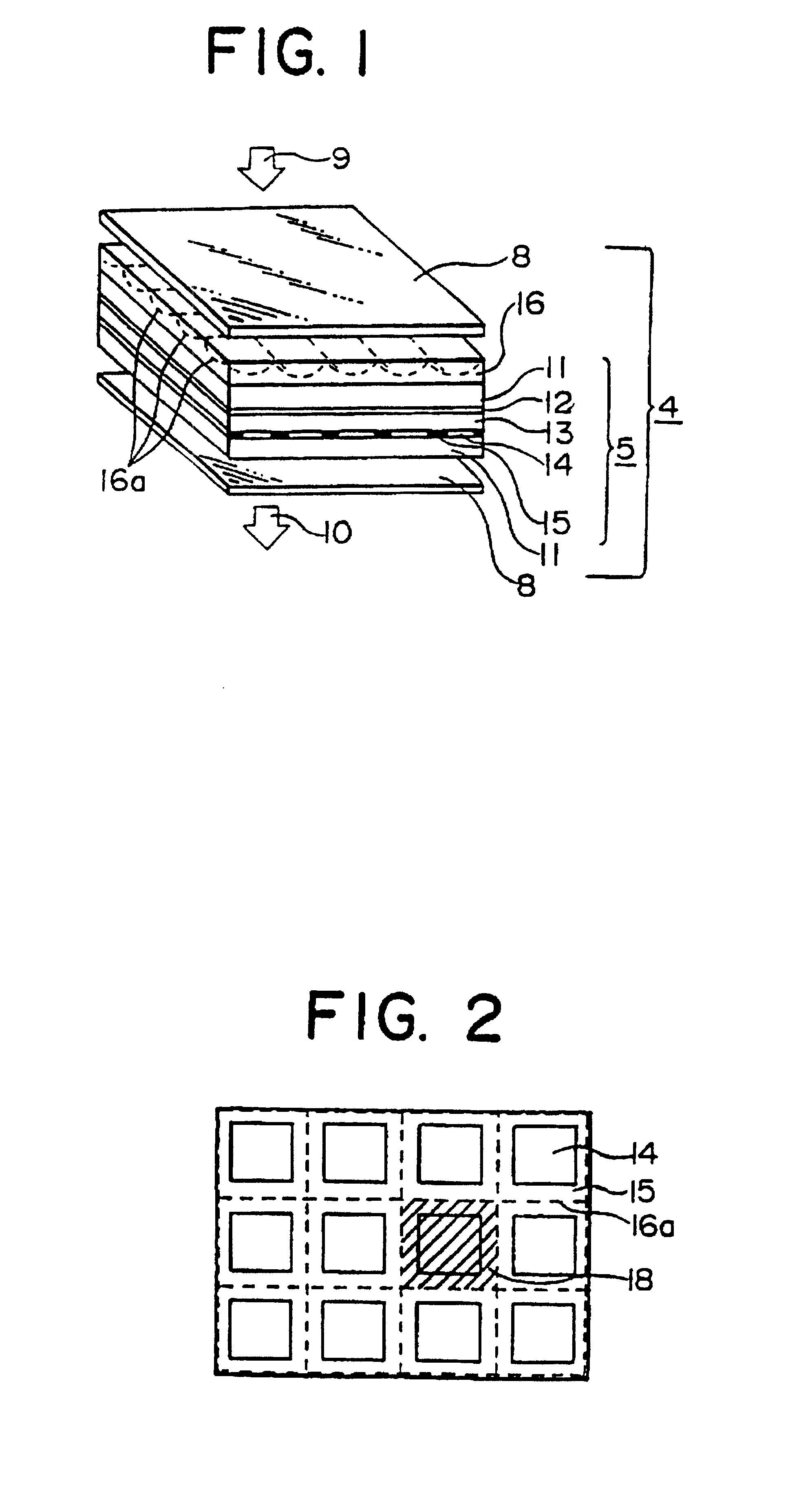
According to the liquid crystal display element of the invention constructed as mentioned above, the incident light is effectively conducted to the picture element electrodes, and is almost not "eclipsed" by the metal wiring of electrodes, nonlinear devices or switching devices added as means for controlling the picture elements individually, and the gaps around the picture element electrodes (light-shielding portions) not contributing to the display. Thus, bright picture information can be displayed even if the aperture ratio is poor (small). In addition, according to this invention, since the light exiting from the liquid crystal display element is only the effective light for the display, the opaque portions between the picture elements are eliminated, and thus picture information can be smoothly displayed.
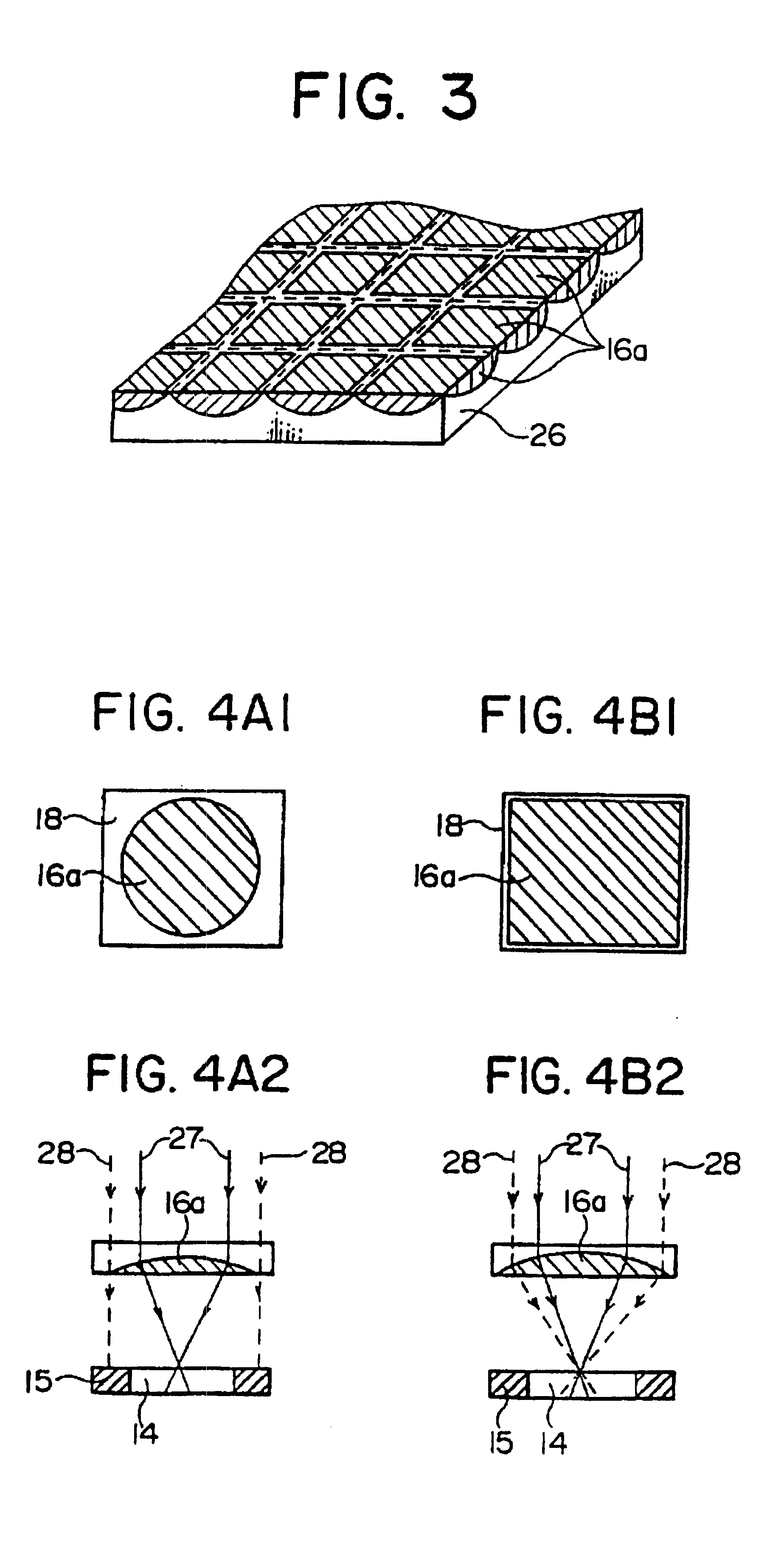
Also, according to the illumination optical system of the above construction, since the light from the light source is once focused by the refractive power of the condenser lens group properly located, and light at around the focal point can be controlled, it is not necessary to increase the aperture of the condenser lens, and the incident angle of light to the liquid crystal display element or the micro-lens array relative to the optical axis can be decreased to improve the focusing characteristic of the micro-lens array, so that the light utilization efficiency can be increased. Furthermore, since the shape of the luminous flux passing through the apertures in the cross-section perpendicular to the optical axis, or the shape of the light source as viewed from the micro-lens, or the shape of the light source in the cross-section perpendicular to the optical axis, is approximately similar to the shape of the apertures, the luminous flux passing through the apertures of the liquid crystal display element covers all the range of the apertures, so that the liquid crystal display has a large aperture ratio, or is able to display bright and clear picture information.

Problems solved by technology

Thus, particularly in this transmission-type liquid crystal display element, the light arrived at the light shielding portions as a part of the light which is emitted from a light source and irradiated on the liquid crystal display element is not transmitted through the liquid crystal display element, and therefore reduces the light-utilization efficiency.
Thus, the effect of the light-shielding portions becomes great, and it is difficult to increase the light intensity.
However, the width of the metal wiring of electrodes and size of additional devices cannot be reduced to a certain value or below from the viewpoint of etching precision and alignment precision.
Thus, all the incident light cannot effectively enter each unit lens portion, and as a result the improvement of the aperture ratio is limited.
Moreover, the liquid crystal display element has generally a large dependency on the visual angle.
However, this is not considered in the above conventional liquid crystal display element and display using the same.

Method used


Image

  • Liquid crystal display element and micro-lens arrangement and a display using the same
  • Liquid crystal display element and micro-lens arrangement and a display using the same
  • Liquid crystal display element and micro-lens arrangement and a display using the same

Examples


second embodiment

FIG. 8 is a perspective view of the liquid crystal display element of the invention. In FIG. 8, like elements corresponding to those in FIG. 1 are identified by the same reference numerals, and will not be described in detail.

Referring to FIG. 8, there is shown the flat-plate micro-lens array 16 which is formed in the one transparent substrate 11 of the liquid crystal cell 5 (integrally formed with the substrate 11). The structure of liquid crystal display element of this embodiment is different in this point from that of FIG. 1. In other words, the transparent substrate 11 which can be apparently maintained at a high precision as described above is satisfactory for the flat-plate micro-lens array 16 of the refractive index distribution type, and thus it is formed within the one transparent substrate 11. The shape of each lens (unit lens 16a) of the micro-lens array 16 is the same as that of the region 18 corresponding to one picture element of the liquid crystal cell shown in FIG. ...

first embodiment

FIGS. 14A, 14D to FIG. 16 show various constructions of the illumination optical system in the liquid crystal display element of the invention shown in FIGS. 13A to 13D.

In FIGS. 14A to 14D, there are shown a concave mirror 2a of a elliptic shape in cross-section or of the so-called multimirror, and a concave mirror 2b of a parabolic shape in cross-section. In the illumination optical system of FIG. 14A, the light emitted from the light source 1 and reflected from the elliptic-shape concave mirror 2a and the light emitted from the light source at about the focal point (hereinafter, called the front-side elliptic focal point) near the center of the concave mirror 2a are focused at around the focal point (hereinafter, called the back-side elliptic focal point) of the elliptic-shape concave mirror 2a near the liquid crystal display element 4. Thus, the condenser lens group 3 as a concave lens having a predetermined positive power is provided near the back-side elliptic focal point on th...

third embodiment

FIG. 22 shows the liquid crystal display using the liquid crystal display element according to the embodiment of the invention as the light bulb.

In FIG. 22, three liquid crystal display elements according to this invention are used to correspond to three colors of R (red), G (green) and B (blue), or so-called three primaries of color and to constitute a three-plate projection type liquid crystal display. Referring to FIG. 22, the light emitted from the light source 1 of, for example, metal halide, xenon or halogen is, directly or after reflection from the concave mirror 2, passed through an infrared-cut filter 45 which reflects infrared light and allows visible light to be passed therethrough. Then, the visible light is incident to the condenser lens group 3 and thereby made substantially parallel to the optical axis. The parallel light exiting from the condenser lens group is fed to a B (blue)-reflecting dichroic mirror 40a which is tilted at 45.degree. to the optical axis. Thus, t...


PUM

PropertyMeasurementUnit
optical lengthaaaaaaaaaa
angleaaaaaaaaaa
transparentaaaaaaaaaa

Abstract

A liquid crystal display includes an illumination optical system which has a light source for emitting light and acts to irradiate the light from the light source on a light bulb on which an optical image is formed in accordance with a video signal, and a transmission-type liquid crystal display element for displaying the image information by the electrooptical effect of the liquid injected between a pair of transparent substrates of the light bulb. The liquid crystal display element is formed of a micro-lens array which has unit lenses provided to oppose the respective picture elements of the picture element array of the liquid crystal and thus to have the same array as the picture element array of the liquid crystal. Since this micro-lens array is closely attached to the side of liquid crystal display element to which the luminous flux emitted from the light source is incident, or integrally formed within the liquid crystal cell substrate, the liquid crystal display element has a high aperture ratio.

Description

BACKGROUND OF THE INVENTIONThis invention relates to a transmission-type liquid crystal display element which is formed by injecting a liquid crystal between a pair of transparent plates and displays picture information by the electrooptic effect of this liquid, and to a liquid crystal display using this transmission-type liquid crystal element as a light valve.The twisted-nematic (TN)-type liquid display element as a typical example of the liquid crystal display element has a liquid crystal cell formed of a liquid crystal injected between a pair of transparent plates with transparent electrodes, and two polarizers which are disposed before and after this liquid crystal cell so that their polarizing directions are 90.degree. different. The amount of transmitted light of the incident light is controlled to display picture information by the combination of the polarizing plane rotating action of the electrooptical effect of the liquid crystal and the polarizing component selecting act...

Claims


Application Information

Patent Timeline
Patent Type & Authority Patents(United States)
IPC IPC(8): G02F1/1335G02F1/13H04N9/31G09F9/35
CPCG02F1/133526H04N9/3105H04N9/312H04N9/315H04N9/3182
Inventor ARIKI, YOSHIOKAKUDA, TAKASHIDEGUCHI, MASAHARUMARUYAMA, TAKESUKEYAMASAKI, FUTOSHI
Owner HITACHT MAXELL LTD
Learn More