System for extending infrared remote control

Inactive Publication Date: 2003-08-05
TERK NEIL D +1
View PDF10 Cites 1 Cited by
  • Summary
  • Abstract
  • Description
  • Claims
  • Application Information

AI Technical Summary

Benefits of technology

An object of the present invention is to provide an improved infrared remote control extender system and / or an associated method for extending the operational range of an infrared remote control unit.
Another object of the present invention is to provide an infrared remote control extension system which is separate from the remote control and accordingly does not impede the emission of the IR signal to local devices.
Yet another object of the present invention is to provide an infrared remote control extension system which can avoid the addition of another electronic object to the visible space in a room.

Problems solved by technology

Accordingly, infrared remote control units are unable to control electronic devices which are disposed around a corner or on a floor different from the location of the remote control.
A problem with the latter kind of RF extenders of infrared remote control units is that the remote control itself is encumbered by an add-on device.
Then the add-on device is prone to misplacement.
Where an IR-to-RF extender is constructed as a separate stand-alone unit, it has the disadvantage of adding additional clutter to an entertainment space.
Another disadvantage of the attached kind of IR-to-RF converter is that each infrared control must have its own converter.
This multiplication of extenders is burdensome and multiplies the shortcomings of a single IR-to-RF converter.

Method used


Image

  • System for extending infrared remote control
  • System for extending infrared remote control
  • System for extending infrared remote control

Examples


Embodiment Construction

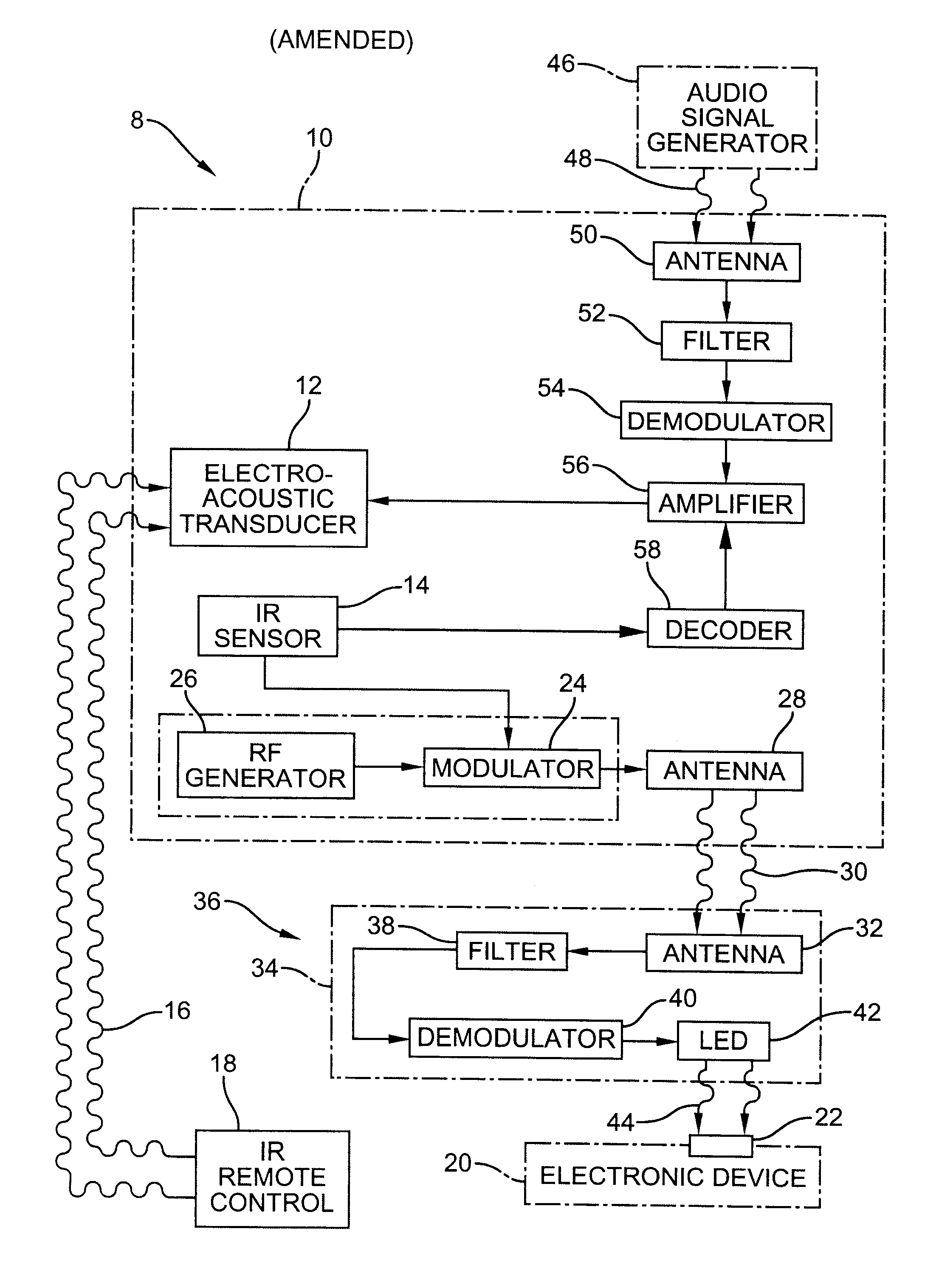
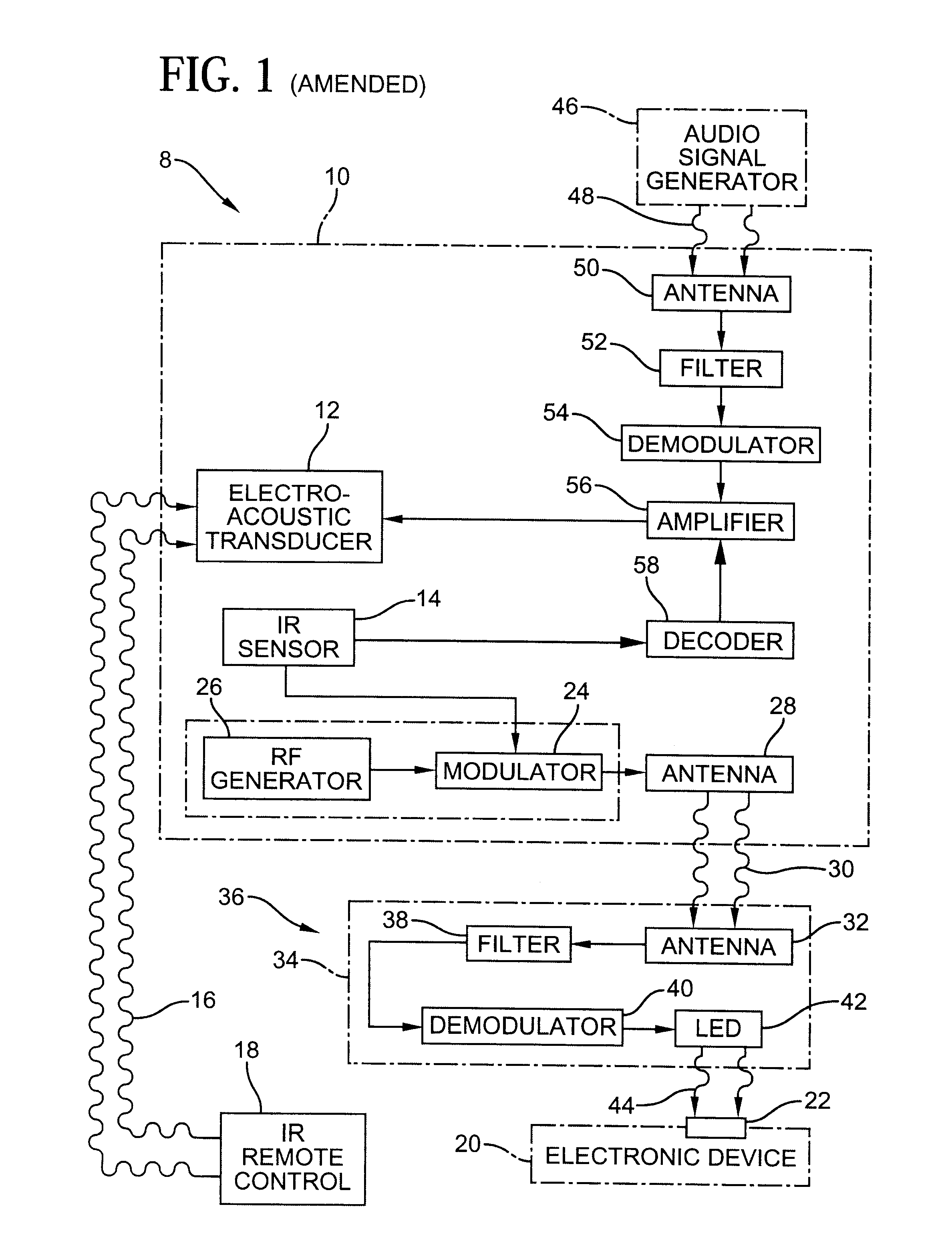
As shown in FIG. 1, an audio speaker 8 of a home audio reproduction system includes a speaker housing 10 which contains an electro-acoustic transducer 12 and an infrared sensor 14. Sensor 14 generates an electrical signal in response to an infrared signal 16 emitted by a manually actuated infrared remote control unit 18. Infrared signal 16 is designed to control the operation of an electronic device 20 such as a satellite dish control box, a cable control box, a VCR, a video camera, etc. It is to be understood that electronic device 20 may include some mechanical components, for example, where the electronic device is a CD player or changer. IR signal 16 cannot be used directly to control electronic device 20 because there is no line-of-sight path between remote control unit 18 and an IR sensor 22 on electronic device 20. Electronic device 20 is, for example, located in a different room from remote control unit 18.

The electrical signal produced by sensor 14 encodes instructions whic...


PUM


Abstract

An assembly or system for effecting control of an electronic device having an infrared sensor for receiving an infrared control signal from a manually actuated remote control comprises, in accordance with the present invention, an infrared sensor for receiving and converting the infrared control signal from the remote control to an electrical signal, the sensor being attached to an audio speaker assembly of an audio reproduction system. A signal generator also attached to the speaker assembly is operatively connected to the sensor for generating an RF carrier signal modulated by control information encoded in the infrared control signal and the electrical signal. A transmission link is provided for transmitting the modulated RF carrier signal from the speaker assembly to the electronic device. A signal receiver disposed adjacent to the infrared sensor of the electronic device receives the modulated RF carrier signal and converts the modulated RF carrier signal to a secondary infrared signal essentially identical to the infrared control signal.

Description

BACKGROUND OF THE INVENTIONThis invention relates to a system which utilizes an infrared remote control unit to control an electronic device. This invention more particularly relates to a system in which the range of the infrared remote control device is extended.Electrical systems which employ an infrared remote control unit necessarily require that an unobstructed linear path exists between the remote control and the electronic device being controlled. Accordingly, infrared remote control units are unable to control electronic devices which are disposed around a corner or on a floor different from the location of the remote control. Of course, many situations arise where it is desirable to control a VCR, a television, a satellite dish receiver, a video cable box, a sound reproduction system or other electronic device from a location shielded from the electronic device.One solution to the problem of remotely controlling an electronic device from a location which has no line of sigh...

Claims


Application Information

Patent Timeline
IPC IPC(8): G08C23/00G08C23/04H04B1/20
CPCG08C23/04G08C2201/40H04B1/202
Inventor TERK, NEIL D.
Owner TERK NEIL D
Why Eureka
Try Eureka