

Tool for the precision machining of surfaces
- Summary
- Abstract
- Description
- Claims
- Application Information
AI Technical Summary
Benefits of technology
Problems solved by technology
Method used
Image

Examples
Embodiment Construction
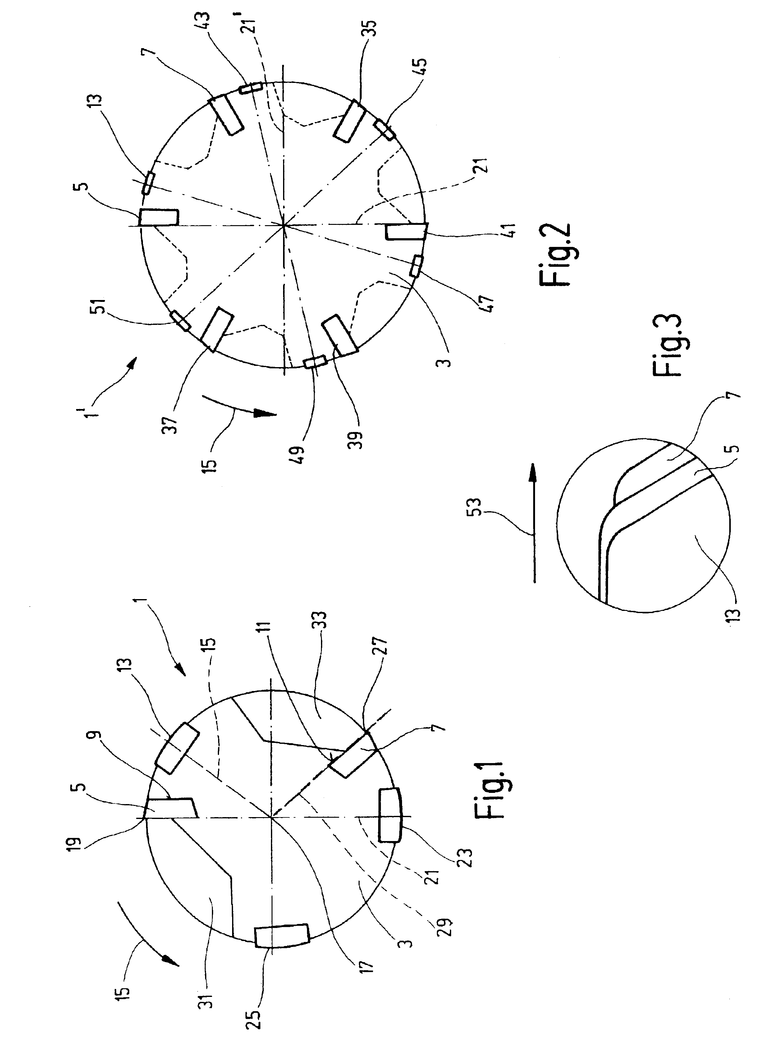
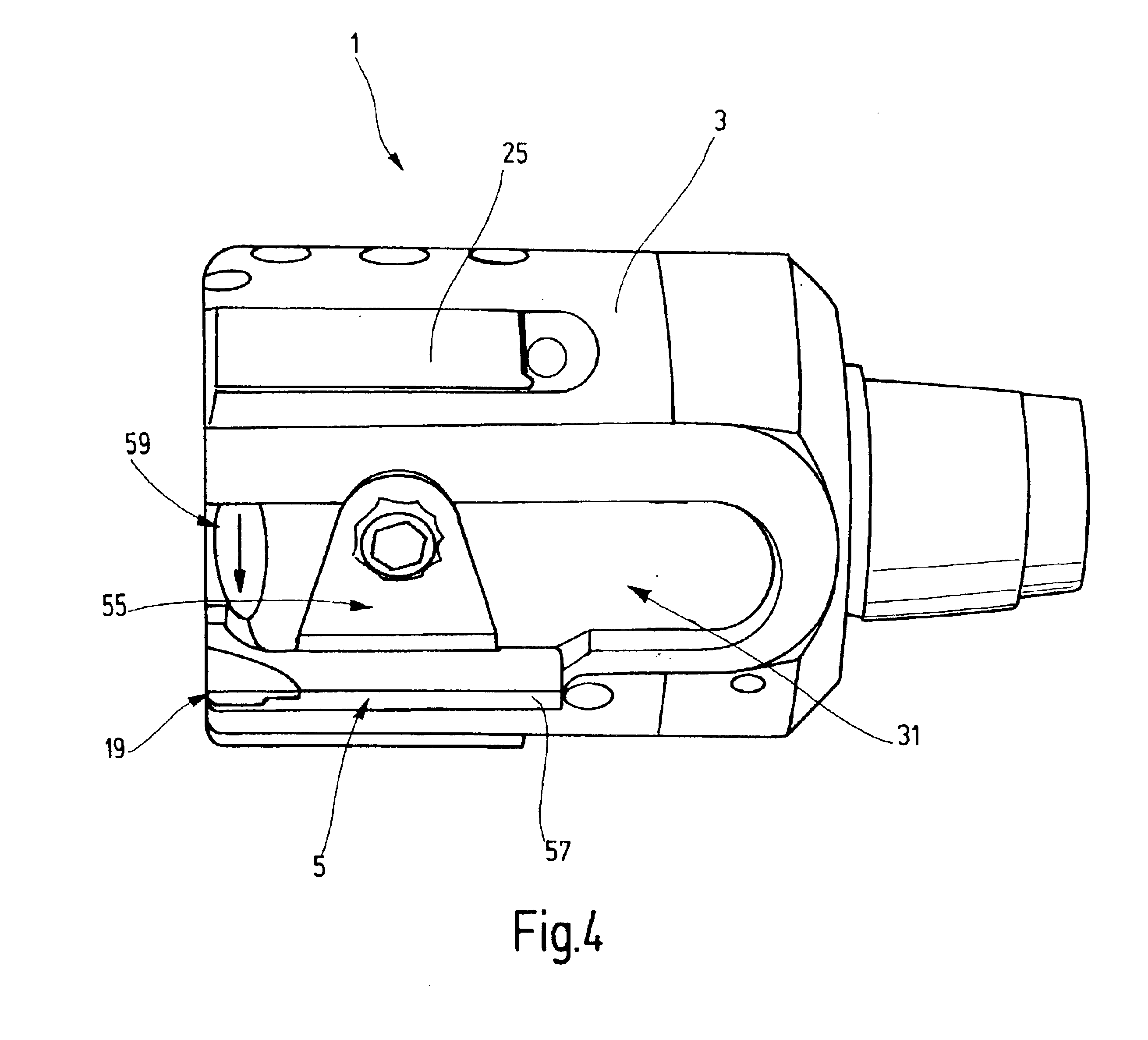
[0014]The tool 1 in FIG. 1 is an example of a two-edged cutter. It has two cutter inserts 5 and 7 which are fastened to the main body 3 of the tool 1 by being inserted into radial grooves 9 and 11 in the main body 3. The cutter inserts 5, 7 are fastened to the body 3 in a conventional manner, usually by clamping shoes. It is also possible to clamp them in place directly on the tool 1 with screws.
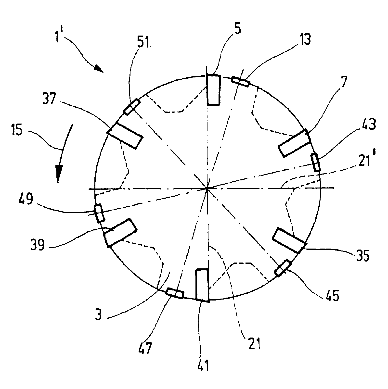
[0015]At least one guide strip is inserted into the main body 3. A first guide strip 13, viewed in the direction of rotation 15 of the tool 1, is positioned behind the first cutter insert 5 by about 40°. A line 15 radially through the center of the guide strip 13 intersects the center axis or rotation axis 17 of the tool 1 and encloses an angle of about 40° with a diametral line 21 through the cutting edge 19 of the first cutter insert 5.
[0016]A second guide strip 23 is positioned opposite the first cutter insert 5. Finally, a third guide strip 25 is inserted into the main body 3 of the tool...
PUM
| Property | Measurement | Unit |
|---|---|---|
| Temperature | aaaaa | aaaaa |
| Temperature | aaaaa | aaaaa |
| Temperature | aaaaa | aaaaa |
Abstract
Description
Claims
Application Information