Light concentrator or distributor

Inactive Publication Date: 2014-07-31
SCHOTT AG
View PDF8 Cites 17 Cited by
  • Summary
  • Abstract
  • Description
  • Claims
  • Application Information

AI Technical Summary

Benefits of technology

The patent describes a technology for making light concentrators or distributors. The technology involves using a special glass or crystal material that can be formed into light conducting bodies by hot molding or other cost-effective methods. The outer shape of the light conducting bodies can be designed to match the optical function of the product. The light conducting bodies can also be produced with desired shapes using known techniques such as injection molding, rolling, or grinding. The technology also involves using 2-dimensional or 3-dimensional wall structures, such as can be made using etching or laser processes, to improve the function of the light conducting bodies. Overall, the technology allows for the efficient and effective production of light concentrators or distributors with a variety of shapes and materials.

Problems solved by technology

Therefore, specifically adapted support structures are required for photovoltaic systems, which are difficult to be integrated in roof surfaces, because of difficulties in sealing against rain.

Method used


Image

  • Light concentrator or distributor
  • Light concentrator or distributor
  • Light concentrator or distributor

Examples


Embodiment Construction

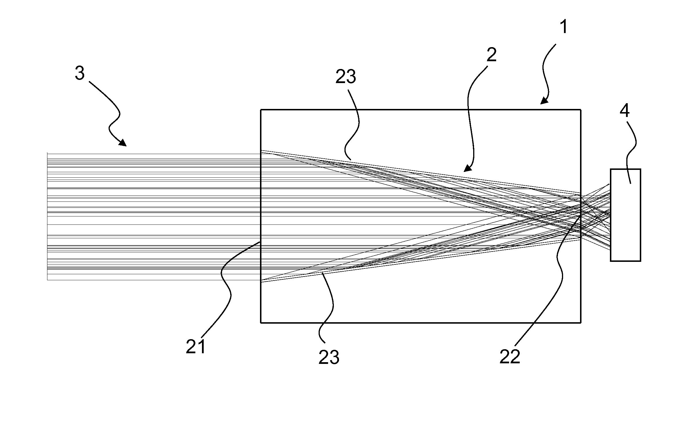
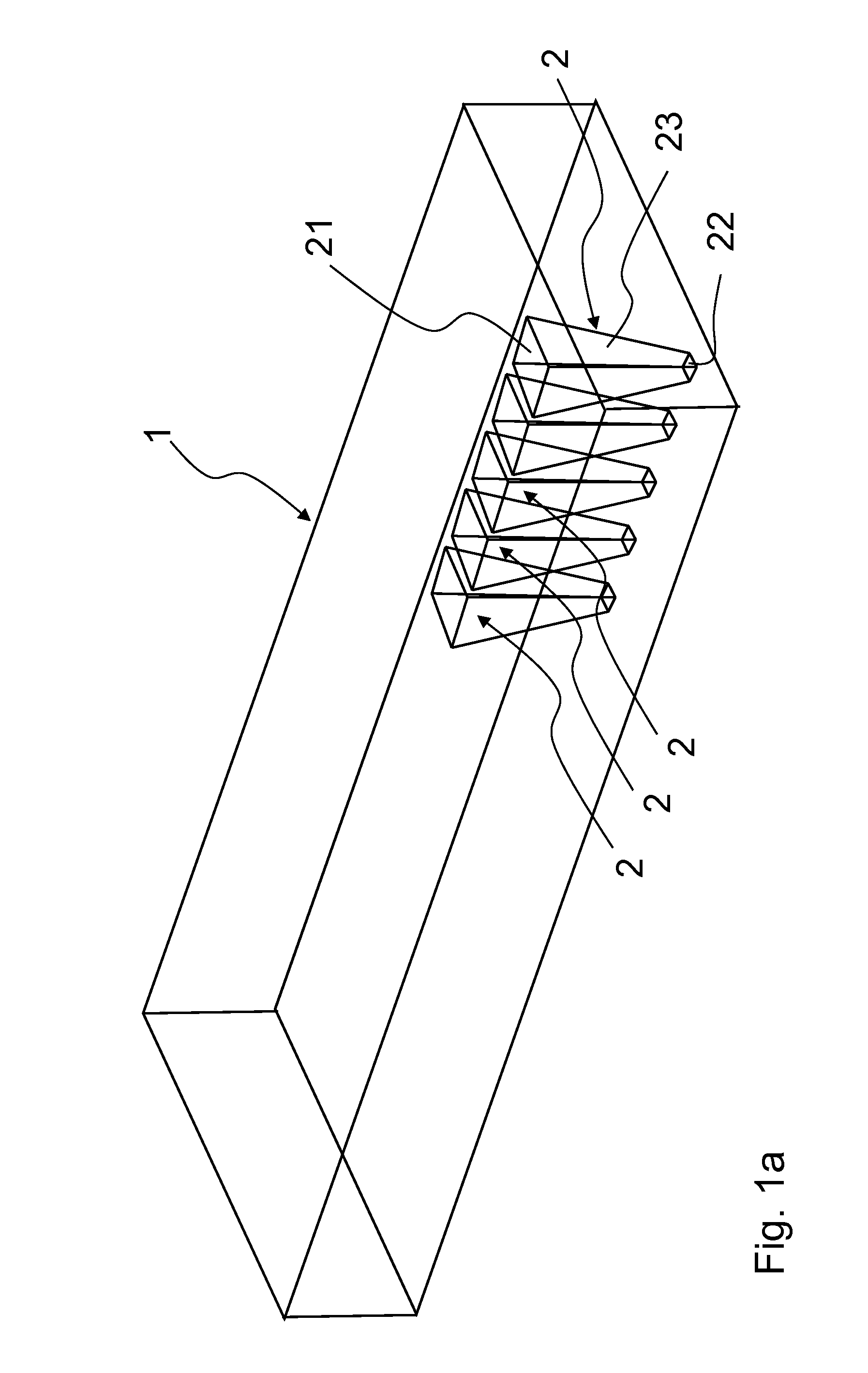
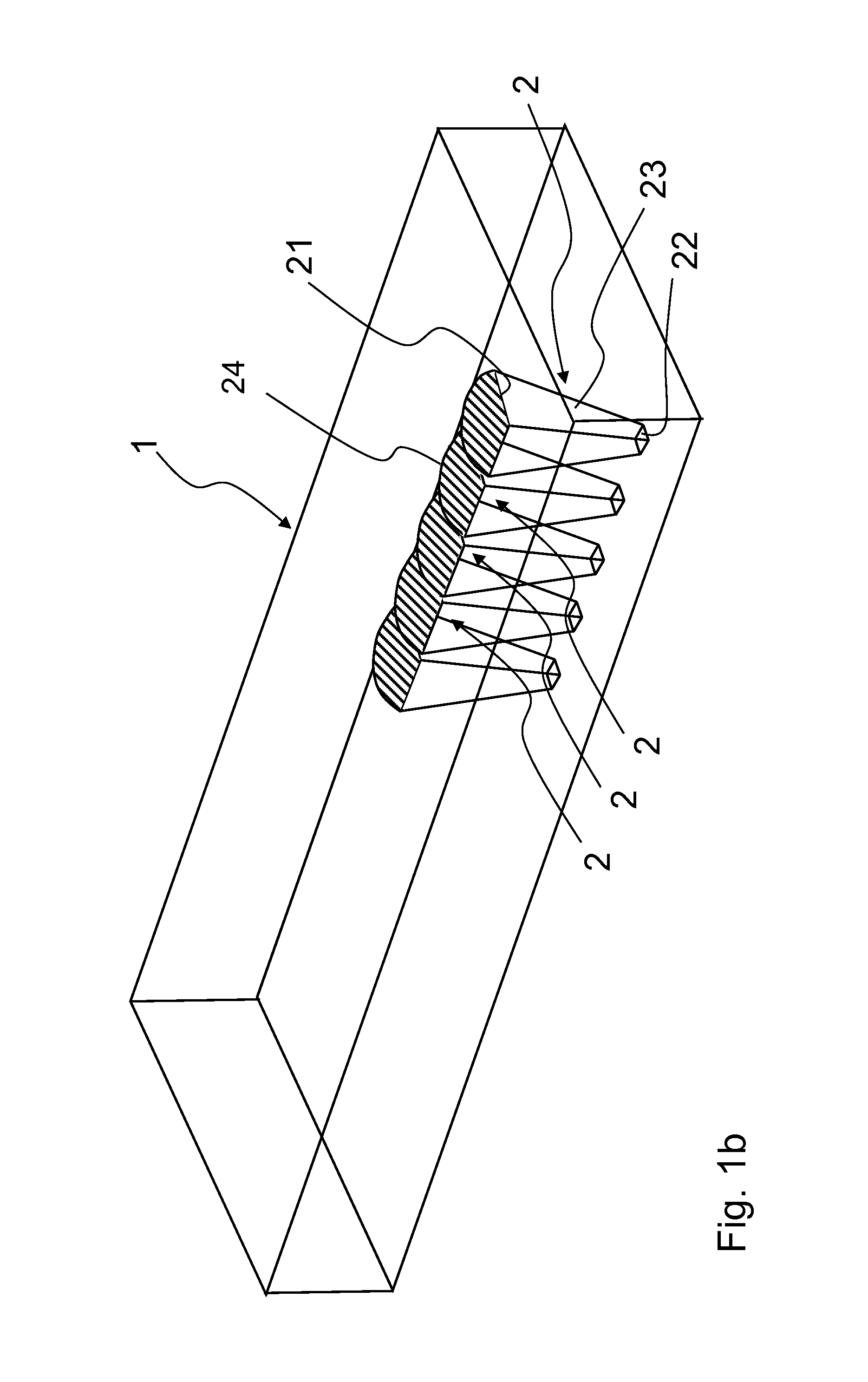
[0033]FIG. 1a is a perspective view of a light concentrator formed as a cell array. A light conducting body 1 of a transparent dielectric material has an upper surface as a light entrance side and a lower surface as a light exit side. Within light conducting body 1, a number of light conducting cells 2 is arranged side by side and forms a linear array of light conductors. Light conducting cells 2 have a shape of truncated pyramids having a major base 21 and a minor base 22 and inclined surfaces as lateral surfaces 23. Bases 21 and 22 may be aligned with the upper or lower surfaces of light conducting body 1, but need not. It is also possible that the minor and / or major base(s) is / are arranged in the interior of the light conducting body, adjacent to the upper and lower surfaces. The following dimensions are possible for light conducting cells 2: edge of major base: from 1 to 100 mm, preferably from 2 to 25 mm; edge of minor base: from 0.2 to 50 mm, preferably from 0.4 to 5 mm, heigh...


PUM

PropertyMeasurementUnit
Fractionaaaaaaaaaa
Timeaaaaaaaaaa
Timeaaaaaaaaaa

Abstract

A light concentrator or distributor is provided, which includes a plurality of light conducting cells that are lined up in a transparent light conducting body. The light conducting cells are defined by boundary faces, which are produced within the light conducting body using laser radiation.

Description

CROSS REFERENCE TO RELATED APPLICATIONS[0001]This application claims benefit under 35 U.S.C. §119(a) of German Patent Application No. 10 2013 100 888.7, filed Jan. 29, 2013, the entire contents of which are incorporated herein by reference.BACKGROUND OF THE INVENTION[0002]1. Field of the Invention[0003]The invention relates to a light concentrator or distributor, in particular of glass, glass ceramics, opto-ceramics, or crystal, for focusing light onto a plurality of light receiving elements or for spreading and collimating light from small area light sources, and also relates to a device including a light source or a photo detector or a photovoltaic cell, and a light concentrator or distributor, and also relates to methods and apparatus for producing such light concentrators or distributors.[0004]The term “light” in the context of the invention does not only refer to visible light, but also to infrared light, ultraviolet light, and X-ray light, if such light is intended to be used ...

Claims


Application Information

Patent Timeline
IPC IPC(8): G02B27/12B23K26/36G02B27/10
CPCG02B27/12G02B27/1073B23K26/365B23K26/03B23K26/0608B23K26/16B23K26/0619B23K26/0624B23K26/064B23K26/389F24S23/00F24S23/12G02B6/4298G02B19/0028G02B19/0066G02B19/0076G02B27/0994H01L31/02325H01L31/055H01L33/505H01L33/58H01L31/0543H01L31/0547Y02E10/44Y02E10/52
Inventor PAWLOWSKI, EDGARBEIER, WOLFRAM
Owner SCHOTT AG
Why Eureka
Try Eureka