Corrosion isolation of magnesium components

Inactive Publication Date: 2009-11-12
GM GLOBAL TECH OPERATIONS LLC
View PDF25 Cites 5 Cited by
  • Summary
  • Abstract
  • Description
  • Claims
  • Application Information

AI Technical Summary

Benefits of technology

[0006]In accordance with embodiments of this invention, a durable oxide conversion coating is formed electrolytically (anodically) on at least those surfaces of the magnesium wheel that are anticipated to be contacted with such a non-magnesium vehicle wheel component. The coating is a magnesium-containing, highly compact oxide layer, integral with the magnesium alloy substrate. The oxide coating may be formed to a thickness up to about 150 micrometers or so to provide its electrical (electrochemical) isolation function. The compact oxide layer is dense, hard, and continuous and effectively isolates the magnesium surface from an attached non-magnesium component. The coating may be crystalline. To the extent that the coating contains pores they are not interconnected to the extent that the isolation function of the coating is impaired. The coating provides protection against wear and galvanic corrosion at the interface of the wheel with other wheel components of dissimilar composition. The oxide coating may contain very small (nanometer size) particles that add to the desirable properties of the corrosion isolation coating on the magnesium wheel surface(s). Such an oxide coating eliminates the need for a separately formed corrosion-impeding insert (for example, an aluminum alloy insert) formed for placement between a magnesium wheel body and another non-magnesium component of the wheel assembly.
[0007]In forming oxide layers on magnesium alloys, species may be added to the electrolyte that give rise to color, hues, or other pleasing appearance characteristics that are noticeable on the magnesium wheel. Metal ions in the electrolyte (e.g., tin ions), for example, may be added, which, upon current reversal durin

Problems solved by technology

Such a coupling often results in corrosive degradation of the magnesium wheel because magnesium is anodic to iron and other materials used in vehicle wheel

Method used


Image

  • Corrosion isolation of magnesium components
  • Corrosion isolation of magnesium components

Examples


Example

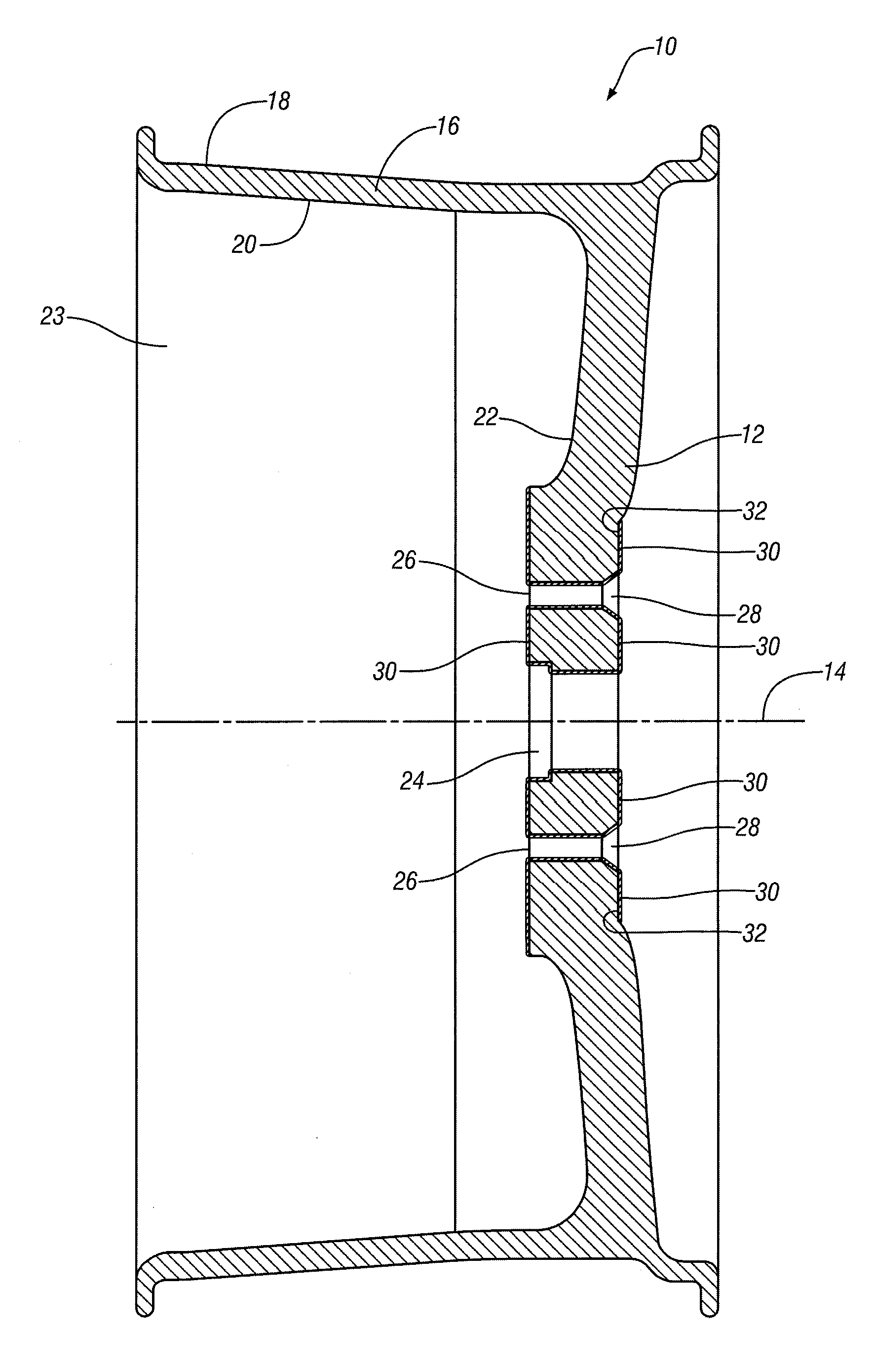
[0012]The drawing FIGURE shows a cross-sectional view of a vehicle wheel 10 which may be formed, for example, of a magnesium alloy formulated for casting or for forging. This includes, but is not limited to alloys such as AZ31B, AZ61A, AZ80A, ZK21, ZK31, ZK60, and ZM21.

[0013]Magnesium wheel 10 has a hub 12 that extends radially from the intended axis of rotation 14 of the wheel. Hub 12 terminates in a round circumferential rim 16. A pneumatic tire will typically be mounted on the radially exterior side 18 of rim 16. The radially interior side 20 of rim 16 and the inboard side 22 of wheel hub 12 define a space 23 to receive other vehicle wheel components (not shown in the FIGURE) when wheel 10 is mounted on a spindle or axle of a vehicle wheel system. In some vehicles wheel 10 may also be mounted to a wheel hub or to a brake rotor. In the illustrative example of the drawing FIGURE, hub 12 of wheel 10 has an axial hole 24 for the end of a wheel spindle (not shown in the FIGURE) and a ...


PUM


Abstract

A vehicle component, such as a wheel, is formed of a magnesium alloy for weight reduction in an automotive vehicle. It is expected that the wheel will be attached to other vehicle wheel-related componenets that are formed of metal compositions (for example, steel or cast iron components) that may lead to the corrosion of the magnesium wheel. Such attachment surfaces of the magnesium wheel are oxidized to form an integral and durable oxide layer on the magnesium wheel. When the magnesium wheel is attached to vehicle wheel supporting components of other alloys, the oxide layer-coated surfaces of the magnesium wheel are electrochemically isolated from the non-magnesium materials to prevent oxidation of the wheel or attached components.

Description

TECHNICAL FIELD[0001]This invention pertains to the adaptation of magnesium components such as automotive vehicle wheels for corrosion isolation from contiguous vehicle parts formed of other materials such as cast iron or steel. Integral oxide layers are formed on surfaces of, for example, magnesium wheels to isolate the wheels from direct surface-to-surface contact with attached different metal parts.BACKGROUND OF THE INVENTION[0002]There is interest in reducing vehicle mass by making magnesium alloy wheels (and other magnesium vehicle components) for automotive vehicles. Reducing vehicle unsprung mass has additional importance (i.e., beyond that of reducing mass for improving fuel economy) in that it improves vehicle ride characteristics. However, the wheels are attached to wheel hubs, brake rotors, spindles, and the like that are not formed of a magnesium alloy. Magnesium tends to form a corrosive galvanic coupling with other metals, such as ferrous alloys, particularly when the ...

Claims


Application Information

Patent Timeline
IPC IPC(8): B60B19/00
CPCB60B3/02B60B3/16B60B3/145B60B3/06Y02T10/86
Inventor KRAJEWSKI, PAUL E.VERBRUGGE, MARK W.SACHDEV, ANIL K.SCHROTH, JAMES G.
Owner GM GLOBAL TECH OPERATIONS LLC
Why Eureka
Try Eureka