Multi-cycle, engine braking with positive power valve actuation control system and process for using the same

a technology of positive power valve actuation and control system, which is applied in the direction of machine/engine, charge feed system, valve arrangement, etc., can solve the problems of braking affecting the performance of engine braking, other internal combustion engine limitations, and inherent limitations of conventional single-cycle engine braking systems, so as to achieve reliable and robust performance, greater control and reliability

Inactive Publication Date: 2006-09-05
JACOBS VEHICLE SYST
View PDF24 Cites 23 Cited by
  • Summary
  • Abstract
  • Description
  • Claims
  • Application Information

AI Technical Summary

Benefits of technology

[0050]It is another object of the present invention to provide a controlled two-cycle braking system that is reliable and robust over the entire operating range of the engine speeds.
[0051]It is another object of the present invention to provide an apparatus that is capable of providing a second engine braking cycle.
[0052]A further object of the present invention is to integrate the compression release-type brak

Problems solved by technology

Conventional single-cycle engine braking systems have inherent limitations.
Other internal combustion engine limitations have emerged in the thirty years since engine braking technology has been introduced.
Emission controls, turbo-chargers, and exhaust braking have affected the performance of engine braking.
In doing so, the work that is done in compressing the intake air cannot be recovered during the subsequent expansion (or power) stroke of the engine.
By dissipating energy developed from the work done in compressing the intake gases, the compression release-type retarder dissipates energy from the engine, slowing the vehicle down.
Regardless of the specific actuation means chosen, inherent limits wee imposed on operation of the compression release-type retarder based on the allowable loads on the engine.
A number of mechanical factors have historically imposed limitations: the temperature of critical engine parts, such as valves; the seating velocity of the valves; push tube loads; cam stress, the power available from the compression release retarder to overcome the instantaneous cylinder pressure at the point of opening and a variety of other factors.
Delaying the opening of the exhaust valve in the compression release event to a point later in the compression stroke, however, also increased substantially the loading placed on critical engine components.
In addition to these pressures, significant environmental pressures have forced engine manufacturers to explore a variety of new ways to improve the efficiency of their engines.
Yet, the demands on retarder performance have often increased, requiring the compression release-type engine retarder to generate greater amounts of retarding horsepower under more limiting conditions.
The use of the exhaust restrictor, however, essentially “kills” the boost available from the turbo-charger, dramatically reducing the amount of air delivered to the engine on intake.
This, in turn dramatically worsens compression release-type engine brake performance.
Moreover, nothing in the Volvo '890 patent teaches or suggests two-cycle braking.
Historically, engine manufacturers have been reluctant to modify their engine configurations to provide a dedicated cam lobe for the compression release-type brake.
In addition, on fuel injected engines, the fuel injector requires additional space on the cam shaft for the fuel injector cam lobe.
This configuration has historically limited the amount of space available to provide additional cams to actuate the compres

Method used


Image

  • Multi-cycle, engine braking with positive power valve actuation control system and process for using the same
  • Multi-cycle, engine braking with positive power valve actuation control system and process for using the same
  • Multi-cycle, engine braking with positive power valve actuation control system and process for using the same

Examples


Embodiment Construction

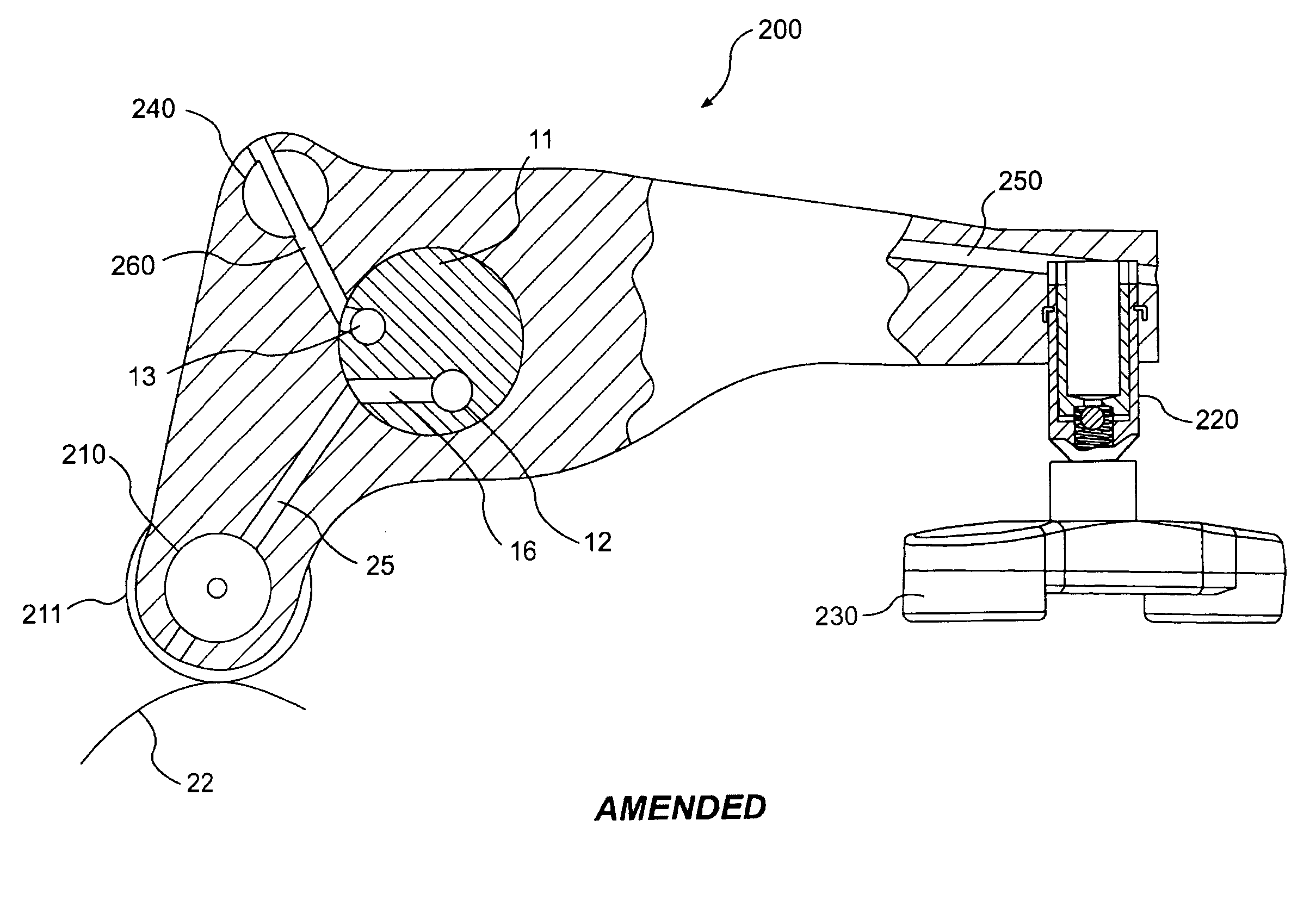
[0087]Reference will now be made in detail to a preferred embodiment of the present invention, an example of which is illustrated in the accompanying drawings. FIG. 4 and FIG. 18 illustrate a schematic view of the valve side of dual cam shafta rocker arm arrangement and dedicated brake cam rocker for a compression release-type engine brake assembly 10 according to the present invention. The compression release engine brake components and the valve actuation components are located in rocker arms 100, 200, and 300.

[0088]The rocker arms 100, 200, and 300 are spaced along a common rocker shaft 11 having at least one passage. The common rocker shaft 11 has a passage 12 through which a supply of engine oil flows therethrough, as shown in FIG. 56. The common rocker shaft 11 also has a supply passage 13 which supplies hydraulic fluid to an exhaust rocker arm 100 and an intake rocker arm 200. A valve 30 is located on the common rocker shaft 11, as shown in FIG. 56. The valve 30 is preferably...


PUM


Abstract

An apparatus and method for effectuating multi-cycle engine braking is disclosed. The present invention controls the operation of the engine valves to permit more than one compression release event during a single engine operating cycle. The apparatus includes an assembly for operating at least one exhaust valve of an engine cylinder during a positive power operation. The apparatus further includes an assembly for operating at least one intake valve of the engine cylinder. The apparatus further including an assembly for operating the at least one exhaust valve during an engine braking operation.

Description

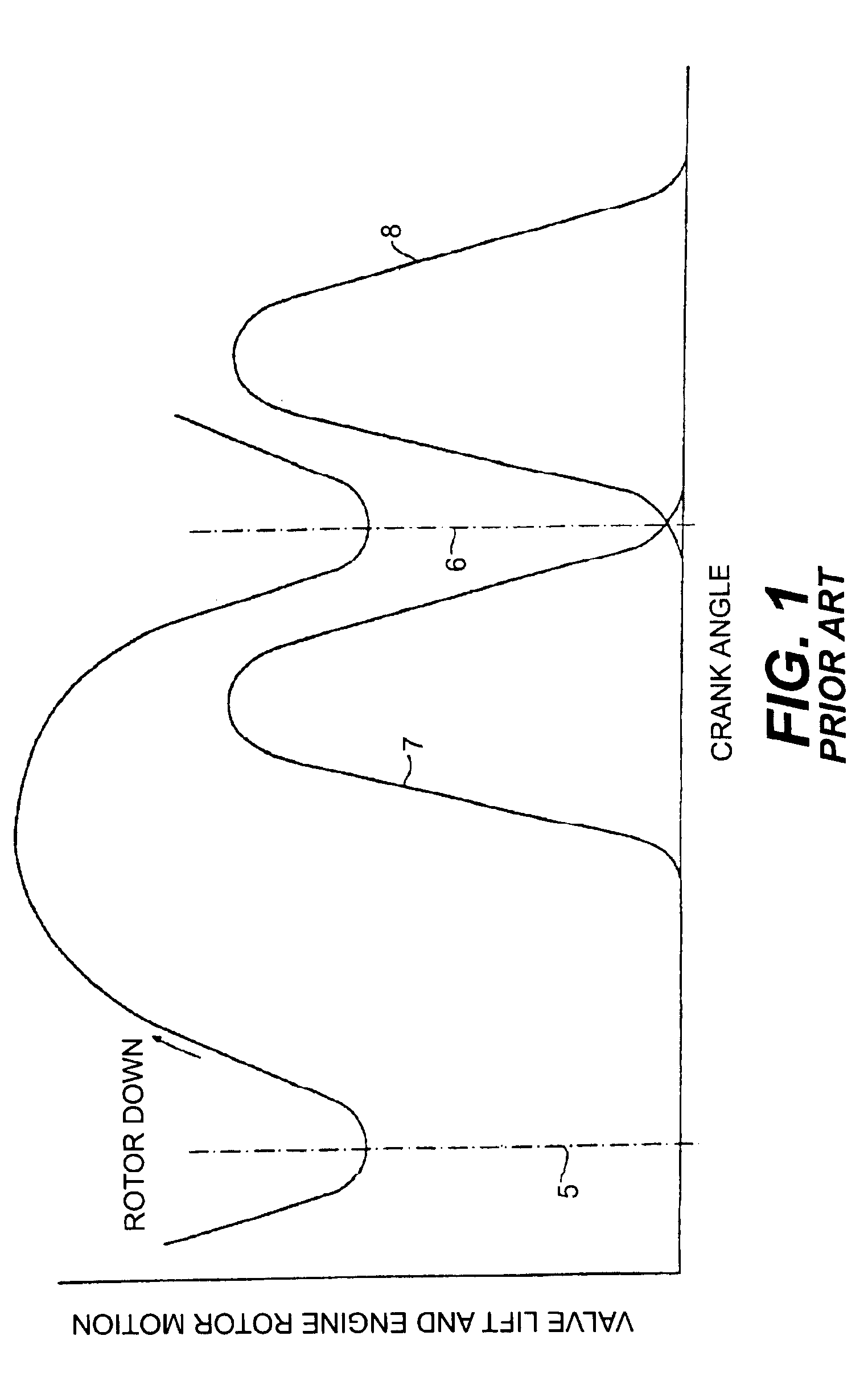
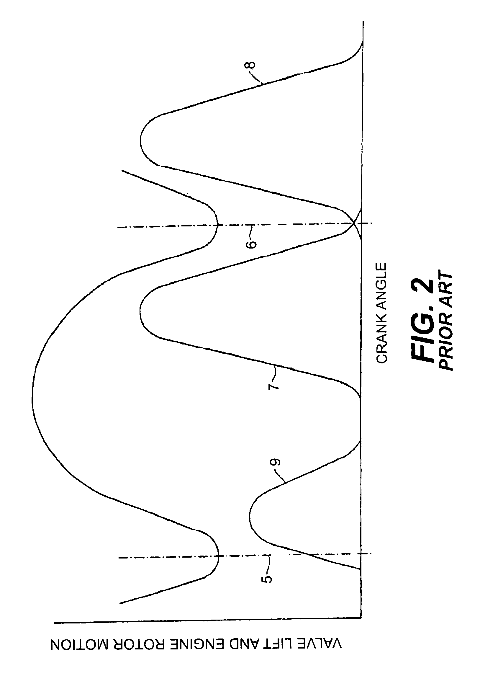
FIELD OF THE INVENTION[0001]The present invention relates generally to the field of compression release engine retarders for internal combustion engines. In particular, it relates to a method for increasing the retarding power of the retarder by generating two braking events, one per engine revolution, for each cylinder of the engine “two cycle braking.” More specifically, the invention involves modifying the cam and rocker arms on a overhead cam engine to provide a dedicated cam lobe for braking. In addition, the classic compression release retarder housing is eliminated and the compression release retarder is associated with the rocker arms.[0002]The exhaust valves of a typical internal combustion engine open at least once during its two-stroke or four-stroke cycle. A second opening of the exhaust valves can be introduced on the compression stroke to achieve additional compression release retarding. The present invention eliminates the first exhaust valve opening on the normal exh...

Claims


Application Information

Patent Timeline
IPC IPC(8): F02D13/04F01L13/00F01L13/06F02D13/02
CPCF01L1/2411F01L1/267F01L1/34F01L1/38F01L13/00F01L13/0036F01L13/065F01L2800/00F01L2800/06F01L2800/10F01L2810/02F02D13/04F02M26/01F01L2305/00
Inventor COSMA, GHEORGHEUSKO, JAMES
Owner JACOBS VEHICLE SYST
Why Eureka
Try Eureka