
Asymmetric superconducting magnets for magnetic resonance imaging

Inactive Publication Date: 2007-01-09
NMR HLDG NO 2
View PDF19 Cites 2 Cited by
  • Summary
  • Abstract
  • Description
  • Claims
  • Application Information

AI Technical Summary

Benefits of technology

[0011]In view of the foregoing, it is an object of the invention to provide high quality MR images and at the same time minimize the sense of claustrophobia experienced by patients and allow better access to patients by attending physicians.
[0013]It is also an object of the invention to provide methods of magnet design and magnet configurations produced by the methods which minimize the difficulties which have existed in the art in designing MRI magnets which have short lengths and / or offset dsv's.

Problems solved by technology

Not surprisingly, many patients suffer from claustrophobia when placed in such a space.
Also, the distance of the patient's head and torso from the end of the magnet system means that physicians cannot easily assist or personally monitor the patient during an MRI procedure, which can last as long as an hour or two.
In addition to its affects on the patient, the length of the magnet is a primary factor in determining the cost of an MRI machine, as well as the costs involved in the siting of such a machine.
Longer magnets require more internal shielding and larger shielded rooms for such safe usage, thus leading to higher costs.
The challenge in designing a compact magnet is the retention of high homogeneity conditions in the dsv, as magnet homogeneity is strongly dependent on the overall length of the coil structure.
The smaller the value of γ, the more difficult it is to obtain a desired homogeneity level in the dsv.

Method used


Image

  • Asymmetric superconducting magnets for magnetic resonance imaging
  • Asymmetric superconducting magnets for magnetic resonance imaging
  • Asymmetric superconducting magnets for magnetic resonance imaging

Examples


Embodiment Construction

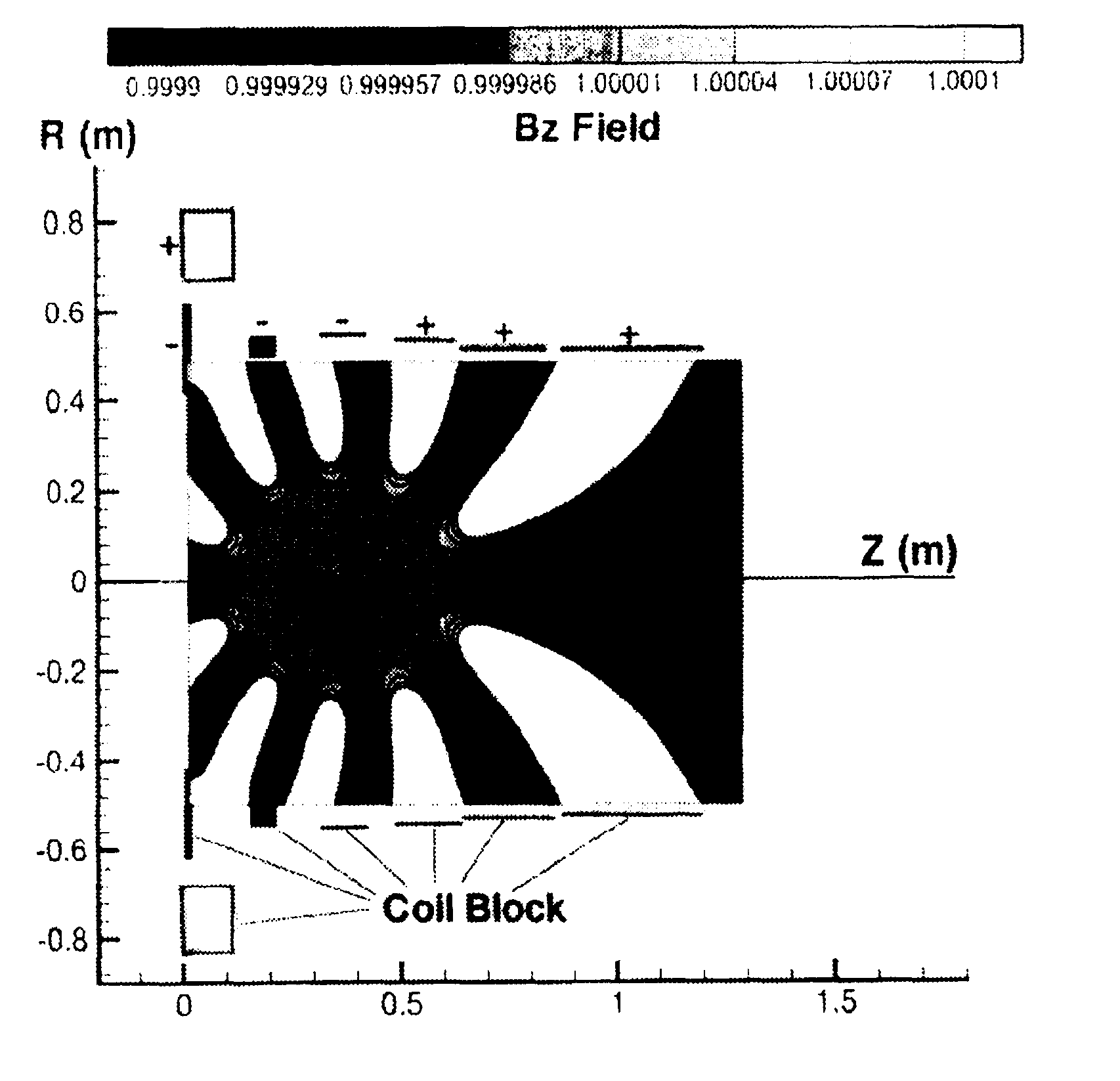
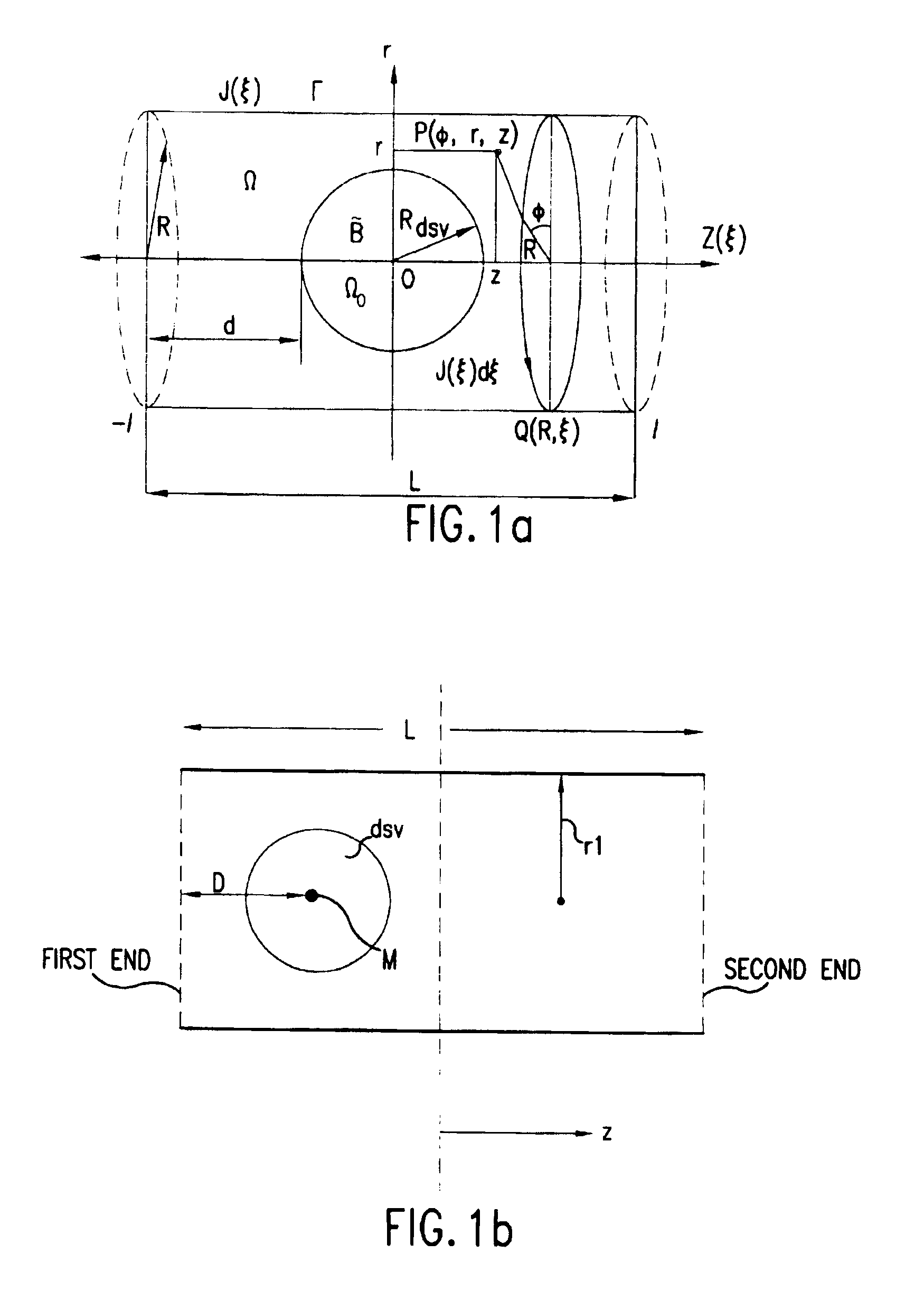
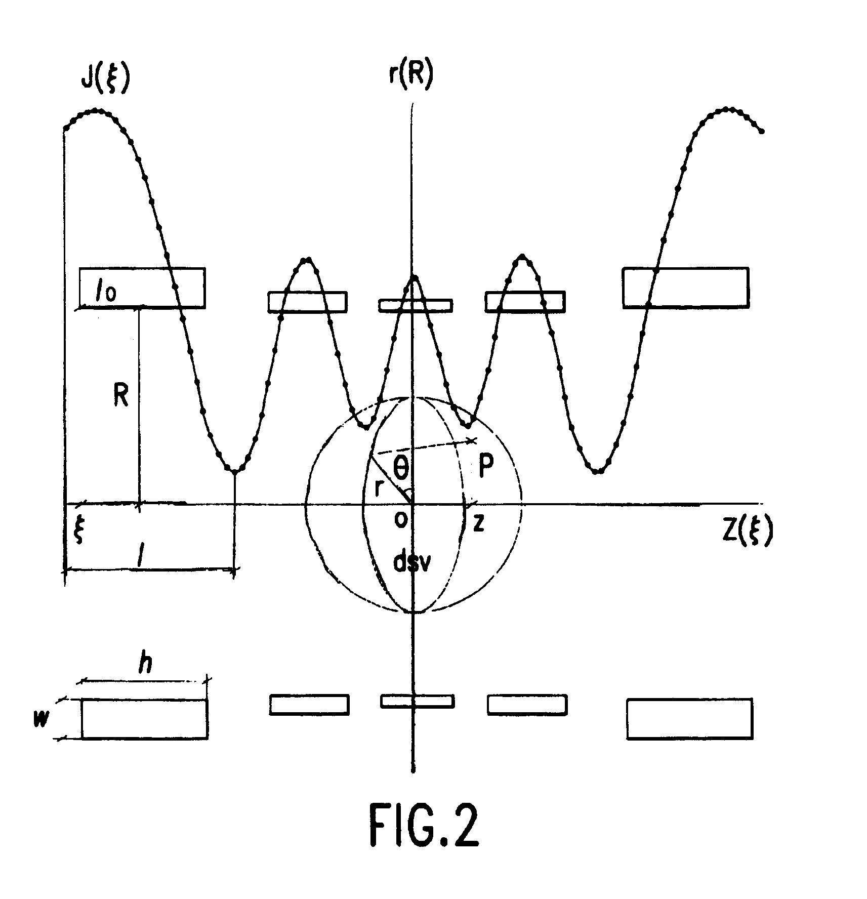
[0071]As discussed above the present invention relates to asymmetric MRI magnets and methods for designing such magnets. The design technique involves two basic steps: (1) use of a current density analysis to obtain a first estimate of coil locations, and (2) use of non-linear optimization to obtain a final coil configuration. For ease of presentation, the method aspects of the invention are discussed below in terms of a single current density layer, it being understood that the invention is equally applicable to, and, in general, will be used with multiple current density layers.

[0072]FIG. 3 illustrates the overall numerical procedure of the invention with reference to the various equations presented below.

I. Current Density Analysis

[0073]In general, the structure of a clinical MRI magnet comprises an air-cored coil. The first step in the method of the invention is to find a source current density which is constrained to the surface of a cylinder of fixed length. In particular, a c...


PUM


Abstract

Asymmetric, compact superconducting magnets for magnetic resonance imaging are provided. The magnets have a homogeneous region (the “dsv”) which can be located close to one end of the magnet so as to reduce the sensation of claustrophobia experienced by patients undergoing MRI procedures. The magnets can be designed using a hybrid process in which current density analysis is performed to obtain an initial coil configuration which is then refined using non-linear optimization techniques to obtain a final coil configuration. The hybrid method can incorporate various constraints, including, the location and size of the dsv, the uniformity and strength of the B0 field, stray field strengths outside of the superconducting magnet, and field strengths within the magnet's coils. The hybrid technique can also be used to design compact symmetric superconducting magnets.

Description

FIELD OF THE INVENTION[0001]This invention relates to a method of magnet design and magnet configurations produced by the method. In particular, the invention relates to asymmetric superconducting magnets for magnetic resonance imaging (MR imaging) and methods for designing such magnets.BACKGROUND OF THE INVENTION[0002]The generation of strong and pure magnetic fields is of great interest in many technical applications. In particular, it is very important for clinical magnetic resonance imaging (MRI). A major specification of the static field in MRI is that it has to be substantially homogeneous over a predetermined region, known in the art as the “diameter spherical imaging volume” or “dsv” Errors less than 20 parts per million peak-to-peak (or 10 parts per million rms) over a dsv having a diameter of 45-50 cm are often required. Conventional medical MRI systems are typically around 1.6-2.0 m in length with free bore diameters in the rnage of 8.0-1.0 m. Normally, the magnet is symm...

Claims


Application Information

Patent Timeline
IPC IPC(8): G01V3/00H01F5/00G01R33/38G01R33/3815
CPCG01R33/3806G01R33/3815
Inventor CROZIER, STUARTDODDRELL, DAVID M.ZHAO, HUAWEI
Owner NMR HLDG NO 2
Learn More