Brush head positioning system

a positioning system and brush head technology, applied in the direction of photosensitive materials, carpet cleaners, instruments, etc., can solve the problems of uneven floor surface, operator's desire, brushes and pads can wear, etc., and achieve the effect of raising and lowering the support and low manufacturing costs

Inactive Publication Date: 2007-04-24
NILFISK
View PDF13 Cites 25 Cited by
  • Summary
  • Abstract
  • Description
  • Claims
  • Application Information

AI Technical Summary

Benefits of technology

[0012]It is another object of this invention to provide a brush head cleaning system which is rugged and low in manufacturing costs but provides efficient positioning of the brush head assembly relative to the floor.
[0021]In another form, the invention comprises an apparatus for use on a surface and responsive to an operator. A vehicle is adapted to ride on the surface. A head assembly on the vehicle is adapted to carry a device for engaging and treating the surface. A support on the vehicle is connected to the head assembly. An actuator on the vehicle is adapted to raise and lower the support. A sensor detects a position of the head assembly relative to the support. A position control, responsive to input from the operator, indicates a desired position of the head assembly relative to the support. A driving circuit responsive to the position control and responsive to the sensor energizes the actuator to raise and lower the support so that the position of the head assembly relative to the support as detected by the sensor corresponds to the desired position as indicated by the position control thereby controlling the relative engagement between the head assembly and the surface and thereby controlling the treatment of the surface by the head assembly. A compressible member of variable length is between the support and the head assembly. The sensor comprises a linear sensor detecting a length of the compressible member.

Problems solved by technology

Often times, the floor surface is uneven, requiring some means for adjusting the brush head to follow the contours of the floor surface.
Also, brushes and pads can wear or the operator may want to change to a different type of brush or pad with different heights.
Such a system may over torque the application of a brush to a smooth concrete floor and may under torque the application of a brush to a rough concrete floor.
In addition, a floor which has a sticky coating on it may be under torqued whereas a floor with a shiny coating on it may be over torqued.
Therefore, monitoring torque or current drawn on brush motors for positioning the brush head is not necessarily an effective technique for accomplishing consistency in the application of force to the floor.
Since the coefficient of friction of the surface may change dramatically, this causes similarly dramatic changes in the current or torque, which changes may be unacceptable.
However, such systems are expensive and difficult to implement in a reliable, industrial grade apparatus.

Method used


Image

  • Brush head positioning system
  • Brush head positioning system
  • Brush head positioning system

Examples


Embodiment Construction

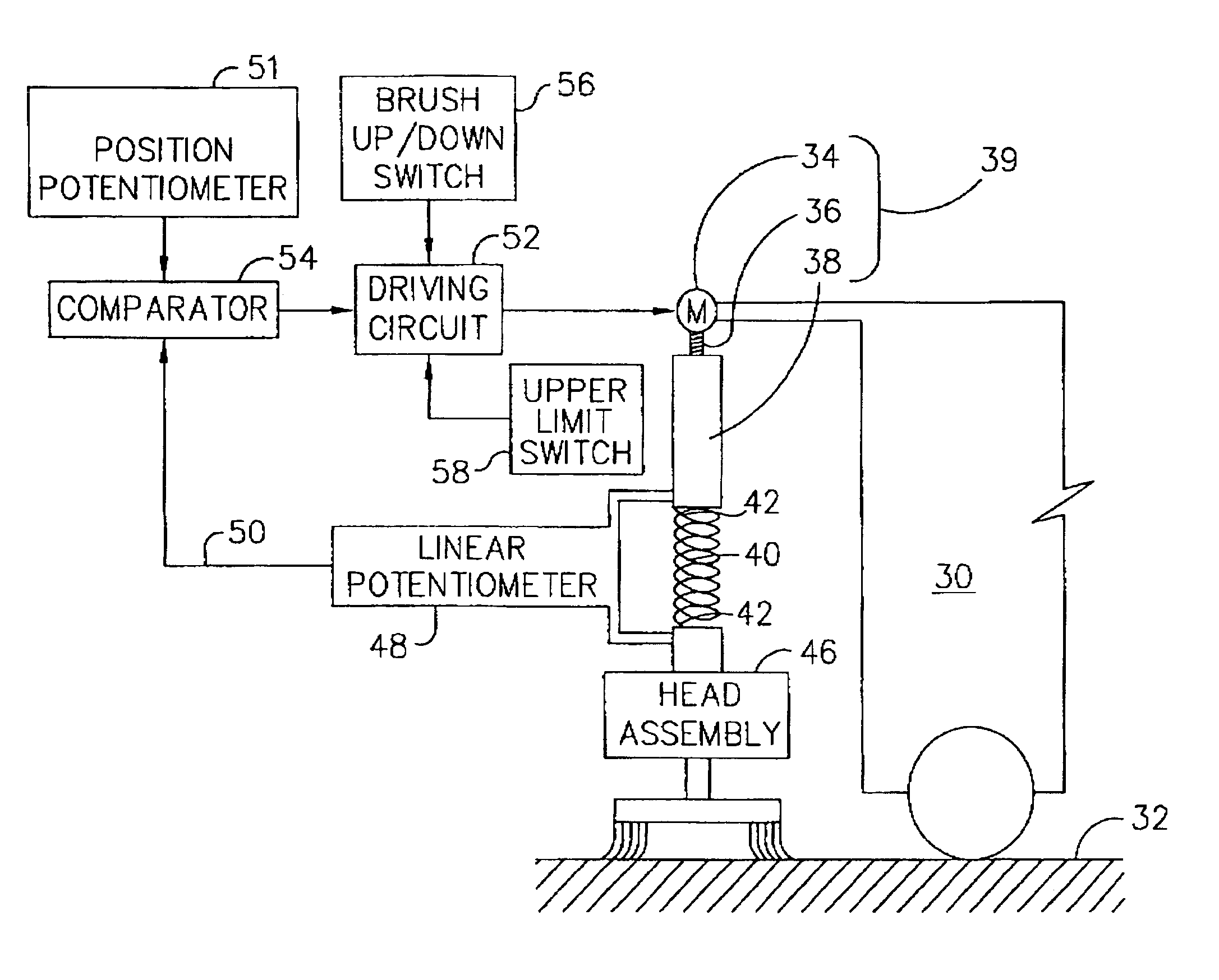
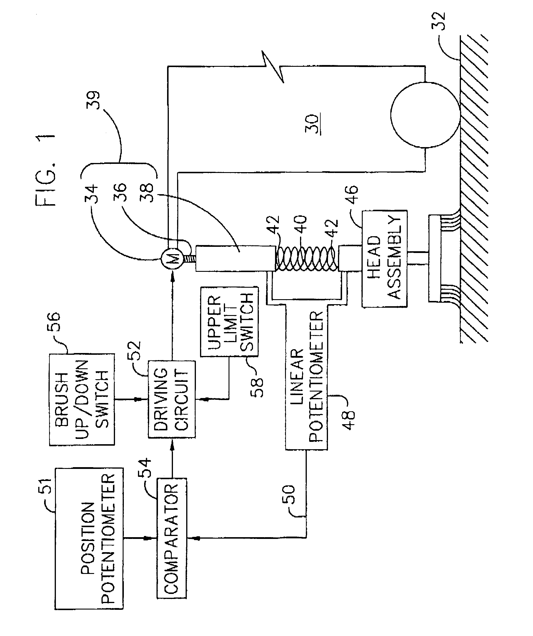
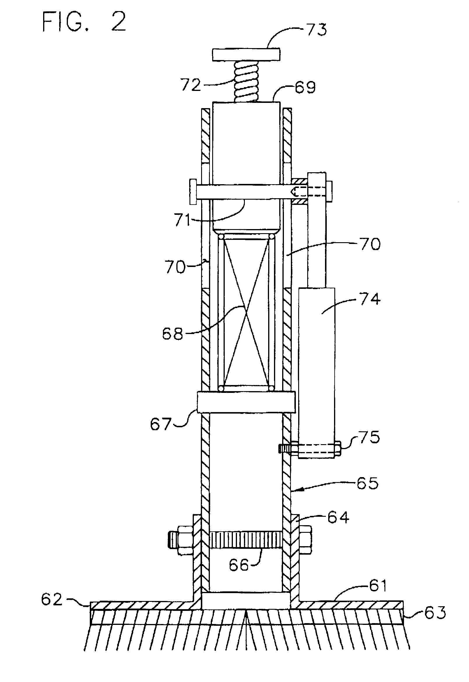
[0040]Referring to FIG. 1, a block diagram of one preferred embodiment of the system according to the invention is illustrated. A vehicle 30 which rests on and traverses a floor 32 (or other surface) supports a motor 34 for driving a screw 36. Rotation of the screw causes a support nut 38 to move upward or downward, depending on the rotation of the screw. A compressible member 40, such as a coil spring, has one end 42 connected to and engaging the nut 38 and has a second end 44 connected to and engaging a head assembly 46. The compressible member is positioned within a tube (not shown). The details of this interconnection between the compressible member 40, the actuator 39 and the head assembly 46 is shown in motor detail i FIGS. 2, 5 and 6 below.

[0041]A linear potentiometer 48 is positioned between the nut 38 and the head assembly 46 and generates a voltage signal via line 50 which indicates the distance between the nut 38 and head assembly 46. This generated signal also indicates ...


PUM


Abstract

An apparatus for use oncomprising a vehicle adapted to move across a surface and responsive to an operator. A head assembly connected to a support on the vehicle is adapted to carry a device for engaging the surface. An actuator on the vehicle raises and lowers the head assemblysupport relative to the surface. A position control responsive to operator input indicates a head position of the device relative to the surface or range of head positions of the devicehead assembly relative to the surfacesupport. The head position or the range of head positions indicates a distance or range of distances, respectively, between the device and the surface. A controller responsive to the position control selectively actuates the actuator or maintain the devicehead assembly in the head position or within the range of head positions as indicated by the position control. As a result, a repeatable position or range of positions of the brush head assembly is obtained, the relative engagement between the head assembly and surface is controlled and the treatment of the surface by the head assembly is controlled. Position control may be used in combination with torque control of motors driving brushes for engaging the surface. Position control may also be used in combination with a pressure control measuring the pressure betweenof the brush head andassembly on the surface.

Description

CROSS REFERENCES TO RELATED APPLICATION[0001]This application is a continuation-in-part of prior U.S. application Ser. No. 09 / 177,311 which was filed on Oct. 22, 1998 (now abandoned), which is based on provisional application No. 60 / 062,710, filed Oct. 22, 1997.[0002]The instant application is a continuation-in-part of U.S. Ser. No. 09 / 177,311, filed Oct. 22, 1998.BACKGROUND OF THE INVENTION[0003]1. Field of the Invention[0004]The invention generally relates to an apparatus for treating a surface which apparatus is responsive to an operator to position a head assembly relative to the surface. In particular, the invention relates to a brush head positioning system for a floor scrubber in which the brush head carries rotating brushes for cleaning the floor and the position of the brush head relative to the floor is controlled.[0005]2. Background of the Invention[0006]When scrubbing floors, it is important to maintain a constant and continuous scrubbing action on the floor. Often times...

Claims


Application Information

Patent Timeline
Patent Type & Authority Patents(United States)
IPC IPC(8): A47L11/16A47L11/283
CPCA47L11/16
Inventor STUCHLIK, WILLIAMDEITERMAN, LENARDCURTIS, MARVINCOURTNEY, GERALDKEAZER, JAMES
Owner NILFISK
Why Eureka
Try Eureka