Modular conveyor system having multiple moving elements under independent control

a conveyor system and moving element technology, applied in the field of conveyor systems, can solve the problems of affecting the scaling of the system, the speed of the belt is typically quite limited, and the pallets are likely to be jarred by strong impact between the mechanical stop and the pallet, so as to achieve the effect of enhancing the scaling properties of the system, reducing the burden on the central controller, and facilitating the movement of the track

Inactive Publication Date: 2007-07-31
ATS AUTOMATION TOOLING SYSTEMS
View PDF39 Cites 48 Cited by
  • Summary
  • Abstract
  • Description
  • Claims
  • Application Information

AI Technical Summary

Benefits of technology

[0020]In the preferred embodiment of the conveyor system, the magnets of each moving elements have a pole pitch P; the electrical pole pitch of each of the coils is P; and the coils of each track section stator armature are arranged in a substantially contiguous sequence of individual polyphase-like sets, each set comprising p overlapping coils having centers thereof spaced apart by a distance P / p, where p>=2, and where coils associated with one track section do not overlap onto an adjacent track section. This enables the track sections to be self contained and modular in nature.
[0021]In the preferred embodiment of the conveyor system, the transfer of the responsibility for resolving the position of a given moving element to an adjacent section controller when the given moving element straddles the corresponding track sections occurs when an aforesaid linear encoder strip is associated with a first linear encoder reader and simultaneously begins to interact with a second, adjacent linear encoder in a second, adjacent track section. The position-detection processing means of each section controller, in combination with the transfer between section controllers of the responsibility for detecting the position of moving elements which cross track sections, enables multiple elements to be tracked along the entirety of the track without requiring any further infrastructure, thereby not posing any undue limits on the number of moving elements which can be tracked. In addition, it will be appreciated that the moving elements are passive devices which, due to not being tethered in any way, have unrestricted mobility along the track.
[0022]In the preferred embodiment of the conveyor system, the section controllers are operative to transfer static data concerning the straddling moving element, such as its destination, to the adjacent section controller prior to the transfer of the responsibility for resolving the position of the straddling moving element. Furthermore, the section controllers are operative to transfer dynamic or memory based servocontrol data concerning the straddling moving element to the adjacent section controller substantially simultaneously with the transfer of the responsibility for resolving the position of the straddling moving element. In this manner, a distributed servocontrol system is presented which enables multiple moving elements to be controlled over a long track.
[0023]In the preferred embodiment of the conveyor system, the sections controllers are connected to a central controller which initializes the system and performs a diagnostic monitoring function. In addition, each section controller is directly connected to a station controller, such as a programming logic controller. The station controllers instruct the track section controllers for the purpose of carrying out station-specific tasks and coordinating the movement of the moving elements with other station machinery. The station controllers can also provide the section controllers with the next destinations for the moving elements, thereby alleviating the central controller from this task. The distributed control architecture provided by these additional components further enhance the scaling properties of the system.

Problems solved by technology

There are a number of fundamental limitations with well-known conventional conveyor systems which employ a belt for transporting pallets between processing stations.
First, the speed of the belt is typically quite limited.
Thus, if the belt conveyor is operated at a high speed, the strong impact between a pallet and mechanical stop is likely to jar whatever parts the pallet may be carrying for processing.
Second, it is generally not possible to vary the acceleration and velocity profiles for individual pallets.
For instance, if a first pallet is empty and a second pallet is loaded with delicate parts, it is generally not possible to aggressively accelerate the first pallet to a high speed while controlling the second pallet using more gentle acceleration and velocity profiles.
This limitation affects the latency and possibly the throughput of the manufacturing line.
Third, belt conveyor is typically not bidirectional, which may result in a suboptimal design of the manufacturing line.
Fourth, the belt conveyor typically provides limited flexibility or programmability, such as being able to very quickly change the positions of processing stations.
Finally, the data acquisition capabilities provided by the belt conveyor are typically quite limited.
For example, it is typically not possible to know where the pallets and their constituent loads are located along the conveyor at all times. Thus, for instance, it may be difficult to know how many pallets are queued at a particular processing station.
Conveyor systems having multiple pallets under substantially independent control are known in the art, but suffer from a variety of limitations.
This makes changing the location of a station a troublesome endeavour.
In addition, the system is not capable of pinpointing the location of a moving pallet at any time.
In view of these limitations, the Takeuchi et al. system does not feature truly independent and total control of multiple moving elements.
First, due to the fact that a separate track of position / commutation sensors is required for each moving element, the system can only accommodate a relatively small number of moving elements.
Second, the length of the linear motor is limited by a servocontrol mechanism, described as a single microcomputer, which can only process and accommodate a limited number of the position / commutation sensors and associated electric current generating control circuitry.
Third, use of the magnetic position-detecting elements provides a relatively poor resolution for measuring the position of the moving element.
Fourth, the winding arrangement of the stator armature is essentially that of a linear stepper motor, which presents an uneven magnetic reluctance along the stator armature resulting in relatively noticeable cogging effects and a jerky thrust production.
Finally, the, coreless design of the stator armature also results in a relatively low average thrust production which may not be suitable for typical conveyor system applications.

Method used


Image

  • Modular conveyor system having multiple moving elements under independent control
  • Modular conveyor system having multiple moving elements under independent control
  • Modular conveyor system having multiple moving elements under independent control

Examples


Embodiment Construction

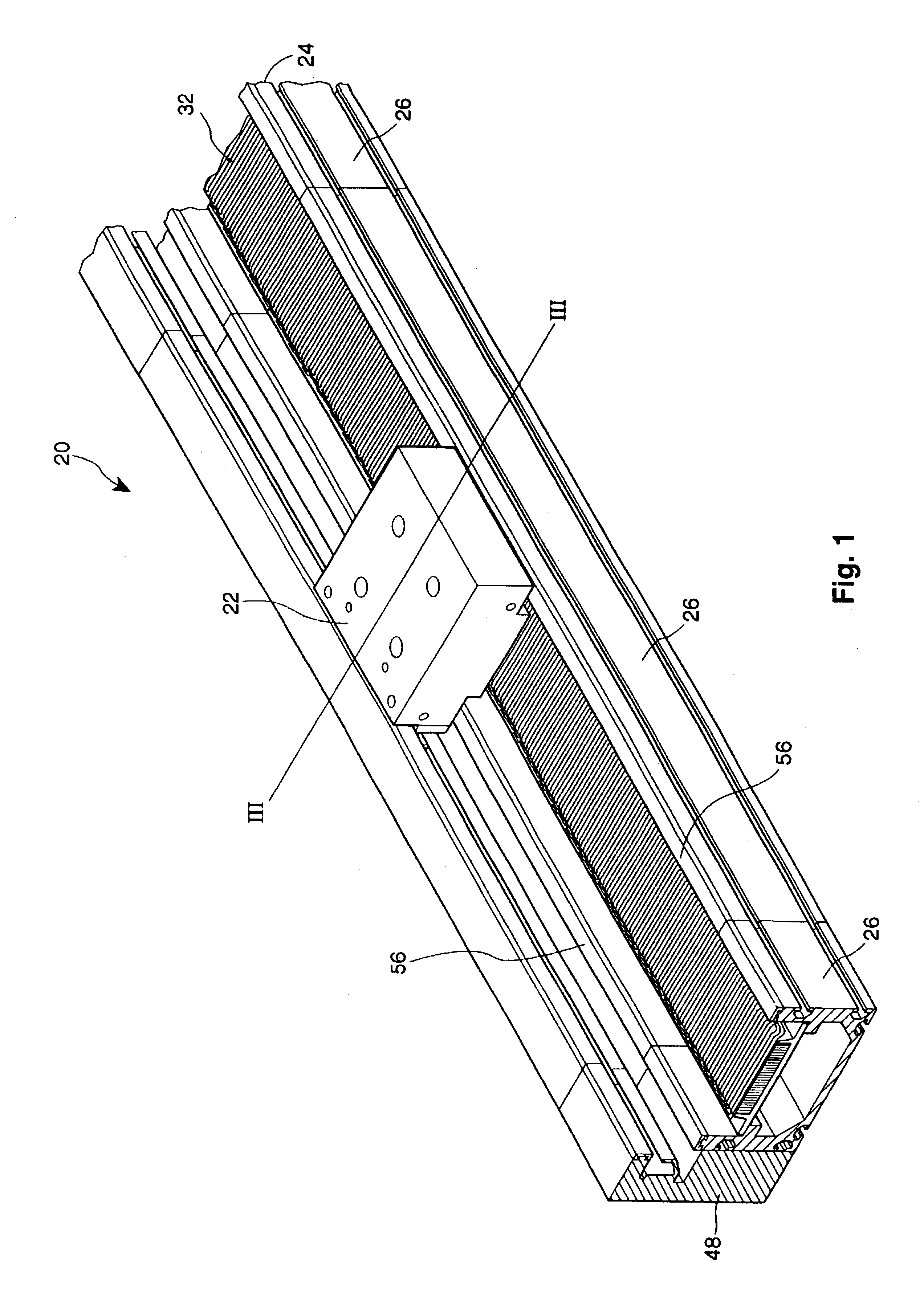
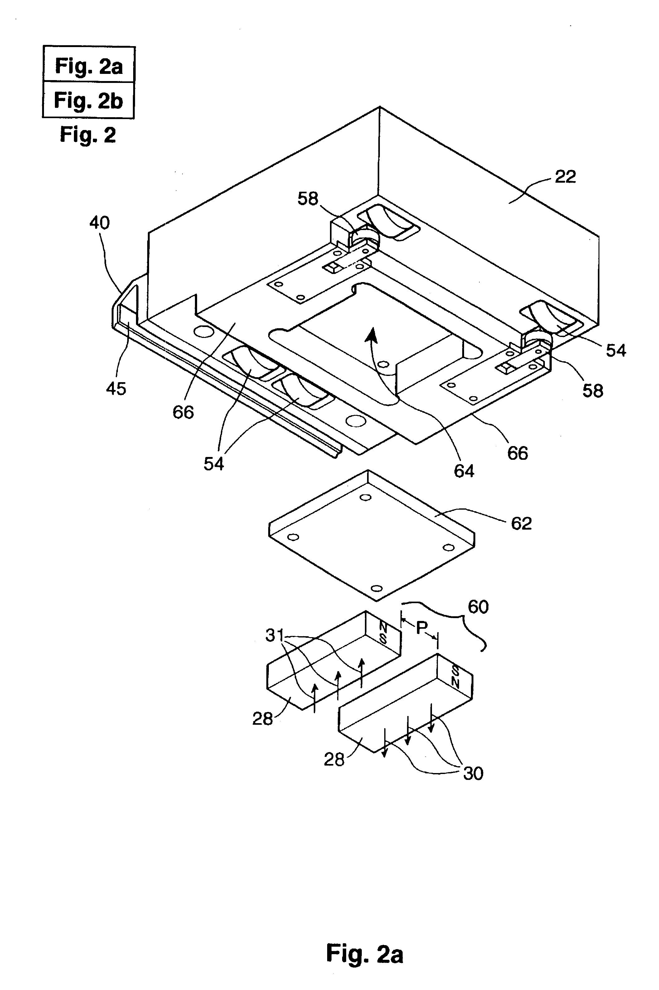
[0040]FIG. 1 illustrates a portion of a modular conveyor system 20, in accordance with the preferred embodiment. The system 20 features multiple pallets or moving elements 22 (only one is illustrated) which are constrained to ride or travel along a continuous, stationary, track 24.

[0041]The description of the conveyor system 20 is organized as follows: (1) an introduction to the operating principles thereof; (2) brief description of the physical structure of the system, which comprises a plurality of track sections or units 26; (3) description of the preferred electromagnetic structure of the system; (4) introduction to a preferred distributed control architecture for control of the system; (5) detailed description of a preferred servocontrol system for each track unit 26; (6) detailed description of a preferred servocontrol subsystem for detecting the position of each pallet 22 along each track unit 26; (7) detailed description of a method according to the preferred embodiment for ...


PUM


Abstract

The modular conveyor system comprises N interconnected track sections, forming a continuous track, wherein each track section features a plurality of individually controlled coils stretching along the length thereof. Plural pallets, each having thrust producing magnets, travel independently alone the track. The track also comprises multiple linear encoder readers spaced at fixed positions therealong, and each pallet includes a linear encoder strip having a length R greater than the spacing E between the readers. Track section controllers associate the encoder strips with only one reader at any time in order to resolve the position of the pallets based on the fixed position of the readers and the relative positions of the strips in relation thereto. The section controllers also regulate and commutate the coils of the corresponding track sections in order to independently control each pallet. Communication links interface adjacent section controllers situated in adjacent track sections. The electromagnetic structure and distributed control architecture of the conveyor system enable it to independently control multiple practical pallets yet be constructed out of modular track sections, with little practical restriction on the length of the conveyor system or the number of pallets controlled thereby.

Description

FIELD OF INVENTION[0001]The invention generally relates to conveyor systems, and more specifically to conveyor systems in the form of modular linear motors having multiple moving elements under independent control.BACKGROUND OF INVENTION[0002]There are a number of fundamental limitations with well-known conventional conveyor systems which employ a belt for transporting pallets between processing stations. First, the speed of the belt is typically quite limited. This is largely due to the fact that the pallets are typically stopped, e.g., in order to be processed at a processing station, by mechanical stop mechanisms. Thus, if the belt conveyor is operated at a high speed, the strong impact between a pallet and mechanical stop is likely to jar whatever parts the pallet may be carrying for processing. Second, it is generally not possible to vary the acceleration and velocity profiles for individual pallets. For instance, if a first pallet is empty and a second pallet is loaded with de...

Claims


Application Information

Patent Timeline
Patent Type & Authority Patents(United States)
IPC IPC(8): H02K41/00B60L15/00B65G54/02G01D3/10G01D5/14G01D5/16G01D5/245G01D5/36H02K41/03
CPCB60L15/00G01D3/10G01D5/145G01D5/2451G01D5/36Y02T90/16B60L2200/26Y02T10/64B65G54/02H02K41/03
Inventor PELTIER, LAURALANKIN, ROBERT GORDONROBINSON, WAYNE MICHAELMACKAY, DAVID KYLEFORTUNA, JEFFREY JOHNMADUSUTHANAN, SAJEEVLINDSAY, SCOTT CHARLESCYBULSKI, MICHAEL A.HANCOCK, MICHAEL J.HOLL, ROBERT A.MOWAT, DONALD J.PELTIER, KENNETH
Owner ATS AUTOMATION TOOLING SYSTEMS
Why Eureka
Try Eureka