

Cellular communications system with sectorization
- Summary
- Abstract
- Description
- Claims
- Application Information
AI Technical Summary
Benefits of technology
Problems solved by technology
Method used
Image

Examples
digital embodiment
All-Digital Embodiment
[0120]Referring now to FIG. 10, there is shown an alternate exemplary embodiment 200 of the present invention. Alternate embodiment 200 includes a remote antenna unit 102 as described with respect to FIG. 8. Remote antenna unit 102 is connected to an all-digital microcell base station 210 through fibers 104A and 104B. Microcell base station 210 is connected to an MTSO.
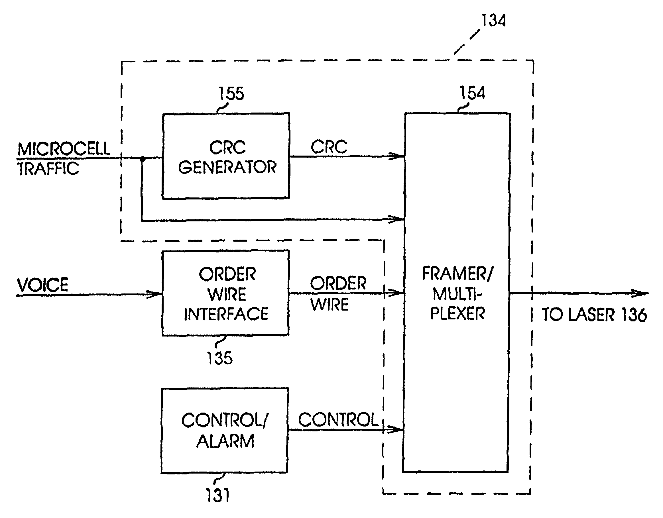
[0121]All-digital microcell base station 210 is shown in more detail in FIG. 11A. Circuit 210 includes a T1 interface 202, which extracts digitized voice channels carried by a T1 line or other carrier from an MTSO and applies those channels in digital form to digital synthesizer 212. Digital synthesizer 212 replaces transmitter 23 and the analog-to-digital converter 132 of the embodiment shown in FIG. 4. Digital synthesizer 212 constructs, with digital logic or software, an equivalent to the digitized output of broadband digitizer 132 for application to frame generator / multiplexer 214. Synthesis m...
PUM
 Abstract
Description
Claims
Application Information