RF power control device for RF plasma applications

a control device and plasma technology, applied in the field of rf power control devices for rf plasma applications, can solve the problems of difficult control of insertion losses in these filters, unreliable methods, and general inability to meet the requirements of plasma generator applications, and achieve the effect of effective isolation of feedback control voltage and greater accuracy

Inactive Publication Date: 2011-11-15
AES GLOBAL HLDG PTE LTD
View PDF23 Cites 60 Cited by
  • Summary
  • Abstract
  • Description
  • Claims
  • Application Information

AI Technical Summary

Benefits of technology

[0011]There is provided by this invention an improved RF power control method for plasma applications that optimizes the feedback control voltage in the presence of harmonic and non-harmonic spurious caused by interaction between multiple generators acting on the non-linear plasma. In this system, an oscillator and mixer are placed at the sampled output of the solid state RF source used for plasma ignition. The sampled output is mixed to an intermediate frequency and filtered to remove the spurious frequencies that are created in the non-linear plasma. In this way, the feedback power control essentially ignores the spurious frequencies. In this application, the oscillator and mixer do not interfere with other desirable system characteristics and effectively isolate the feedback control voltage from changes in plasma spurious frequency content. This allows RF power to be delivered to the plasma with greater accuracy than would otherwise be possible with conventional power control methods

Problems solved by technology

Heretofore, RF power generators used in plasma applications have relied on relatively simple diode peak detectors operating from the output of a directional coupler to monitor the power delivered to the plasma However, this method becomes unreliable in the presence of plasma induced spurious frequencies because the diode detectors cannot differentiate between the voltage of the generator output frequency and that of the plasma induced spurious frequencies.
Synchronous detection methods have been used to eliminate the effect of spurious frequencies, however the cost and complexity of such a design is generally not acceptable for plasma generator applications.
However, insertion losses in these filters are difficult to control, particularly when the offending frequency is very close to the generator output frequency.
However, design of these filters is very difficult when the spurious frequencies are very close to the generator output frequency.
For example, if the spurious frequency has an amplitude that is higher than the generator output and this signal is close in phase to the output frequency of the generator that is being fed back to monitor the power delivered, the peak diode detectors cannot distinguish between the true feedback signal and the signal of the spurious frequency.

Method used


Image

  • RF power control device for RF plasma applications
  • RF power control device for RF plasma applications
  • RF power control device for RF plasma applications

Examples


Embodiment Construction

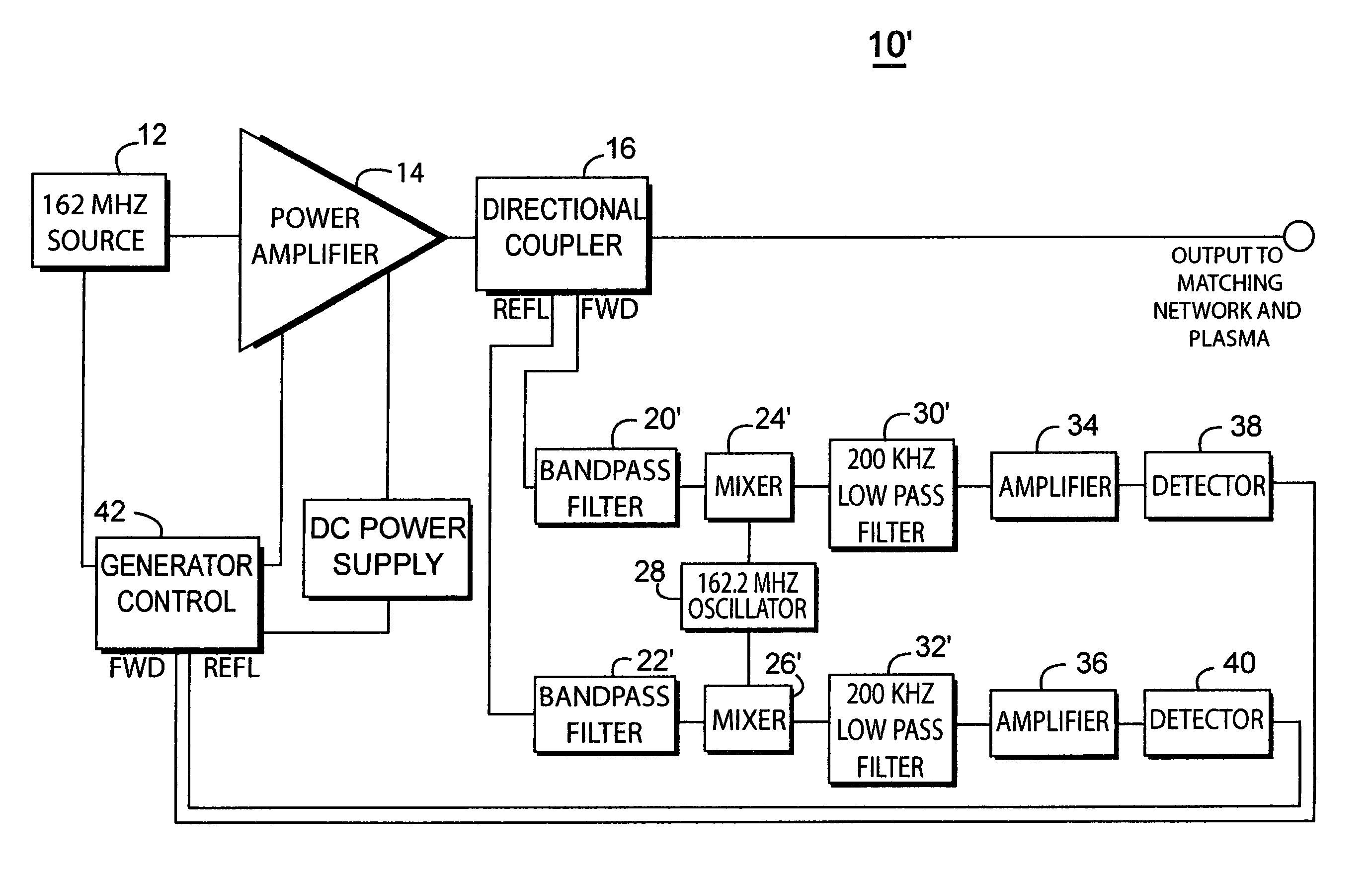
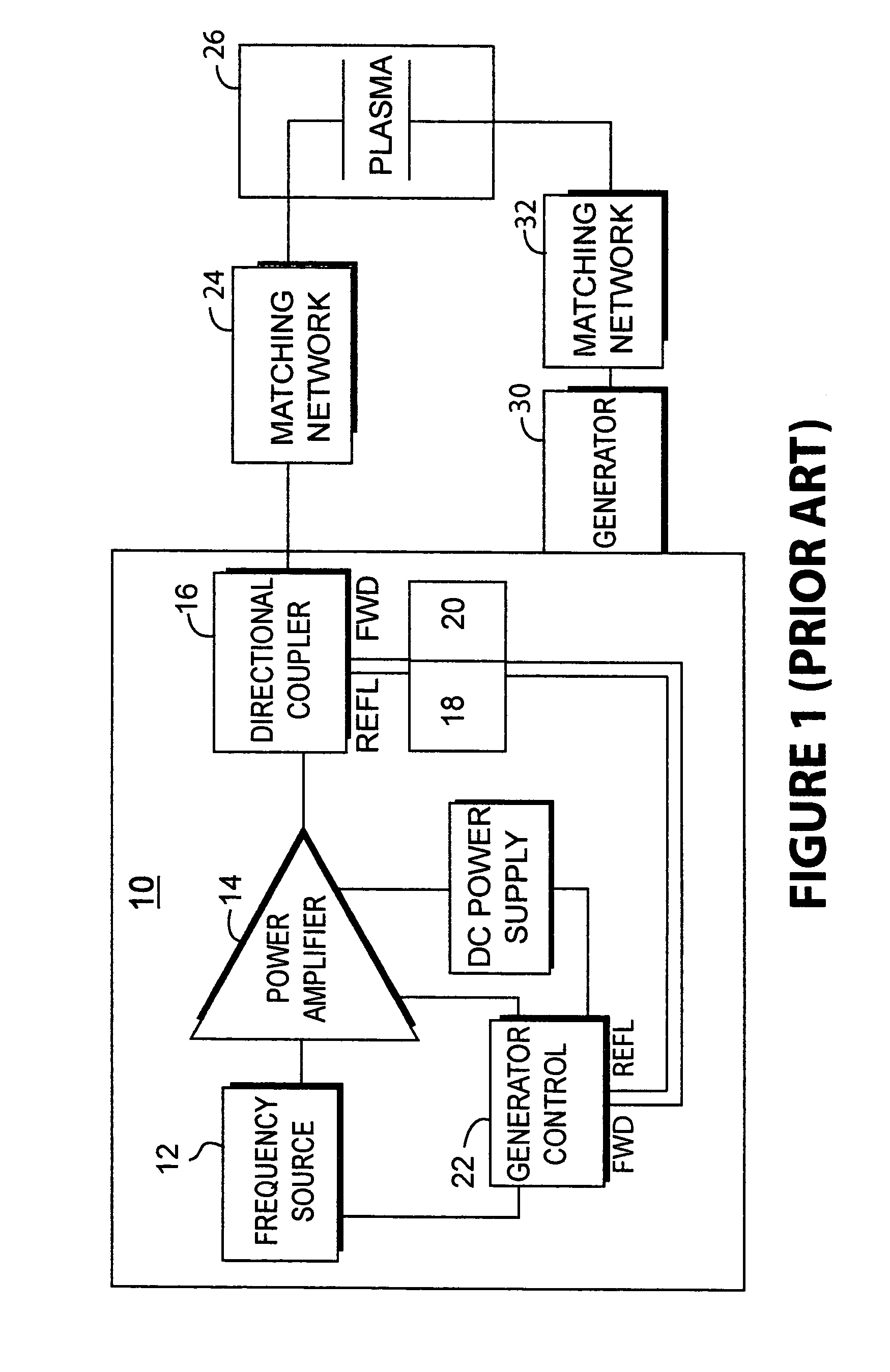
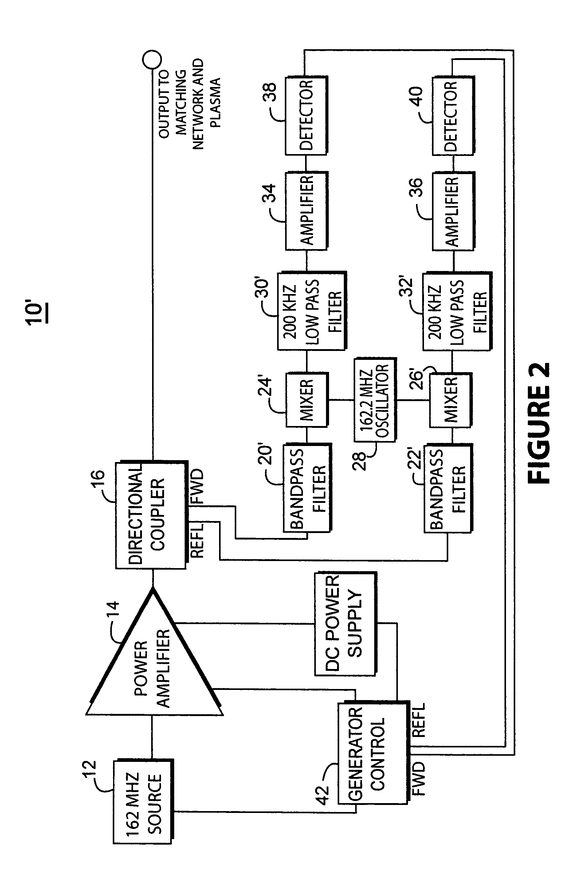
[0016]There is shown in FIG. 2 a VHF generator 10′ that incorporates the principles of this invention that detects and monitors the power delivered to plasma in a plasma processing system such as that shown FIG. 1. In this preferred embodiment a 162 MHz rf source 12 is connected to the power amplifier 14 and sends power to the directional coupler 16. Sampled 162 MHz forward and reflected signals are taken from the directional coupler 16 and injected into the detector circuit where these signals are mixed with a base frequency. The detector circuit is comprised of band pass filters 20′, 22′, mixers 24′, 26′; and a heterodyne oscillator 28. The mixed frequencies are passed through low pass filters 30′ and 32′ there they are amplified by amplifiers 34 and 36 and detected by detectors 38 and 40. The detected signals are then fed back to a generator control circuit 42. This heterodyne detection circuit allows the output of the generator at 18 to be constantly adjusted for changing plasma...


PUM

PropertyMeasurementUnit
frequencyaaaaaaaaaa
oscillator frequencyaaaaaaaaaa
frequencyaaaaaaaaaa

Abstract

There is provided by this invention an improved rf power control device for plasma applications for optimization of the feedback control voltage in the presence of harmonic and non-harmonic spurious frequencies. In this system, an oscillator and mixer, similar to those normally used in radio receiver applications are placed at the sampled output of the solid state rf signal source used for plasma ignition. The sampled output is mixed to a low frequency and filtered to remove the spurious frequencies that is created in the non-linear plasma. In this way, the feedback power control essentially ignores the spurious frequencies. In this application, the oscillator and mixer do not interfere with other desirable system characteristics and effectively isolate the feedback control voltage from changes in plasma spurious content. This allows rf power to be delivered to the plasma with greater accuracy than would otherwise be possible with conventional power control device and methods.

Description

BACKGROUND OF THE INVENTION[0001]1. Field of the Invention[0002]This invention relates generally to plasma processing applications utilizing RF power and more particularly to RF power generators used in plasma processing applications having circuitry to improve power delivery characteristics.[0003]2. Brief Description of the Prior Art[0004]Heretofore, RF power generators used in plasma applications have relied on relatively simple diode peak detectors operating from the output of a directional coupler to monitor the power delivered to the plasma However, this method becomes unreliable in the presence of plasma induced spurious frequencies because the diode detectors cannot differentiate between the voltage of the generator output frequency and that of the plasma induced spurious frequencies. Synchronous detection methods have been used to eliminate the effect of spurious frequencies, however the cost and complexity of such a design is generally not acceptable for plasma generator ap...

Claims


Application Information

Patent Timeline
Patent Type & Authority Patents(United States)
IPC IPC(8): H01J7/24H01P5/08C23C16/00H01J37/32
CPCH01J37/32082H01J37/32174
Inventor HAUER, FREDERICKBEIZER, THERESAMAVRETIC, ANTON
Owner AES GLOBAL HLDG PTE LTD
Why Eureka
Try Eureka