
Receive processing with network protocol bypass

a network protocol and receive processing technology, applied in data switching networks, store-and-forward switching systems, instruments, etc., can solve the problems of affecting the performance of the system, affecting the performance of the personal computer architecture, and putting significant load on the memory subsystem in the computer, so as to reduce the number of times the payload is used

Inactive Publication Date: 2014-08-12
HEWLETT-PACKARD ENTERPRISE DEV LP
View PDF15 Cites 0 Cited by
  • Summary
  • Abstract
  • Description
  • Claims
  • Application Information

AI Technical Summary

Benefits of technology

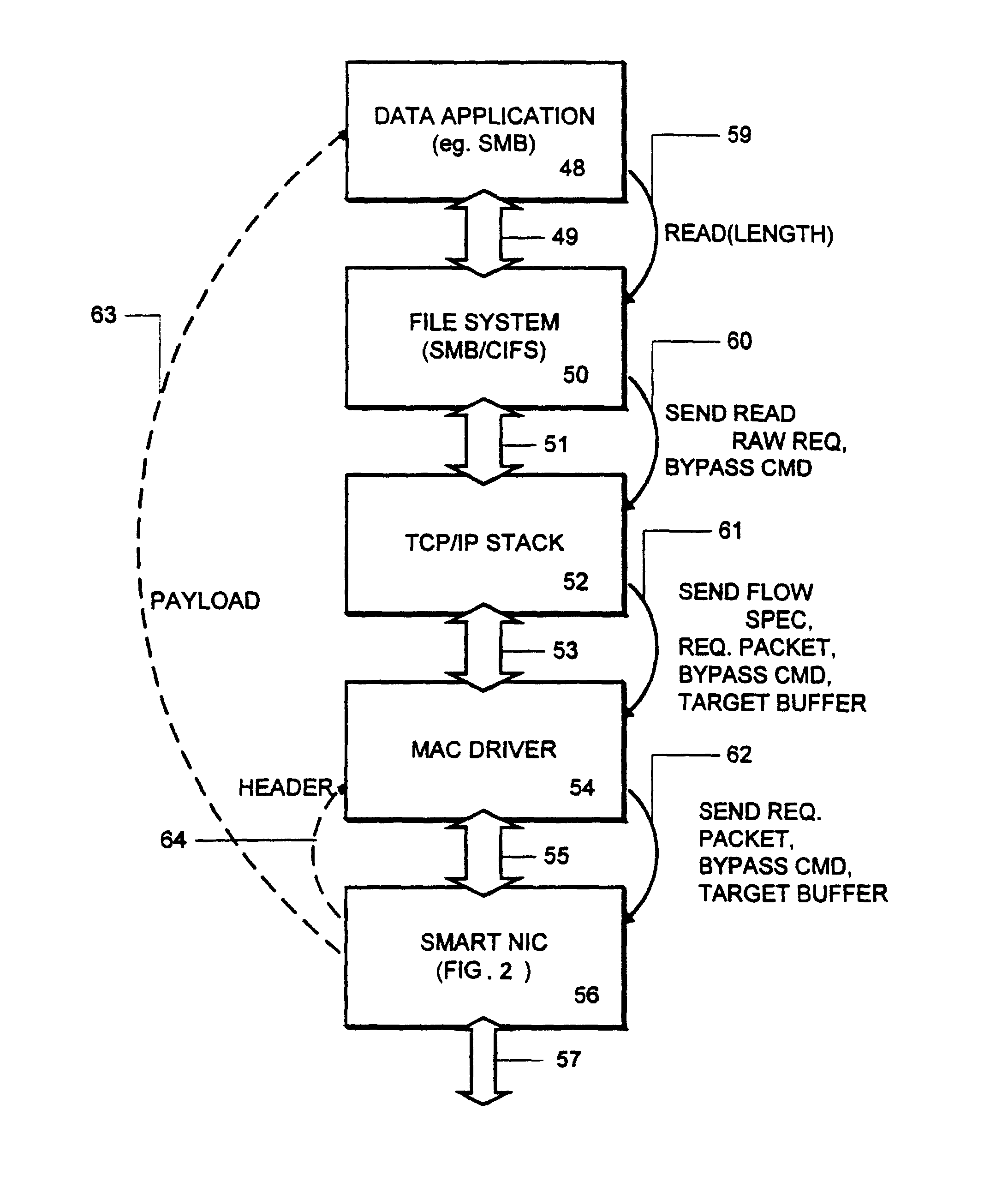
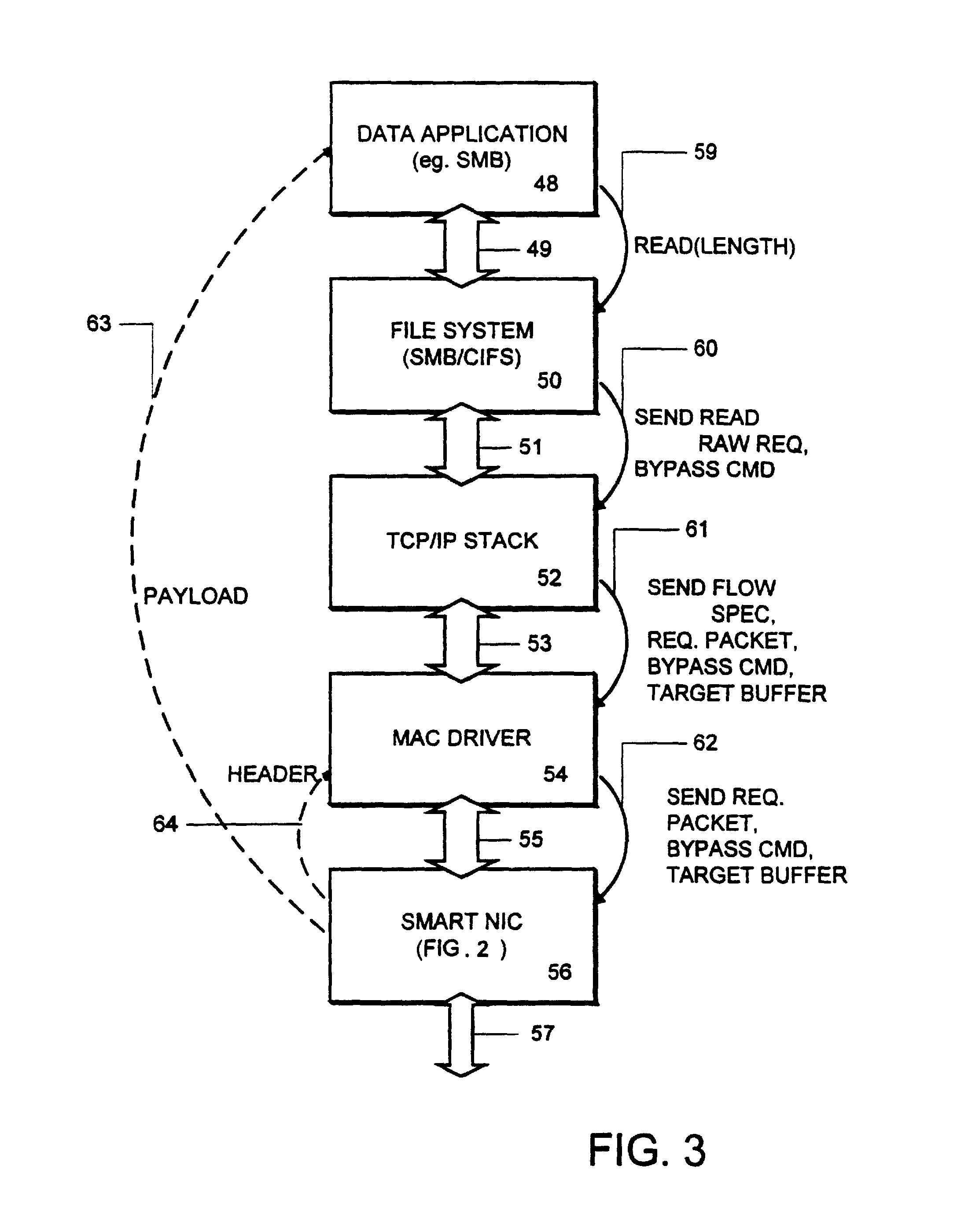
[0010]According to the present invention, an adapter is provided with intelligence that allows it to separate the header parts of a packet being received from the payload it carries, and in most cases move the payload directly into a destination buffer at a higher layer, such as the application layer. Thus reducing the number of times that the payload of a communication must be copied by the host system.
[0014]Accordingly, the present invention provides a technique by which the performance and scalability of a network installation, like a TCP / IP installation, can be improved, especially for high physical layer speeds of 100 megabits per second or higher. Also, the invention is extendable to other protocol stacks in which a read bypass operation could be executed safely.

Problems solved by technology

However, these multiple copies of the data hurt performance of the system.
In particular, the CPU of the computer is used for each copy of the packet, and a significant load is placed on the memory subsystem in the computer.
With technologies like gigabit Ethernet, and other technology in which the data rates of the physical layer of the network is increasing, these copy operations may become an important limiting factor in improving performance of personal computer architectures to levels approaching the capability of the networks to which they are connected.

Method used


Image

  • Receive processing with network protocol bypass
  • Receive processing with network protocol bypass
  • Receive processing with network protocol bypass

Examples


Embodiment Construction

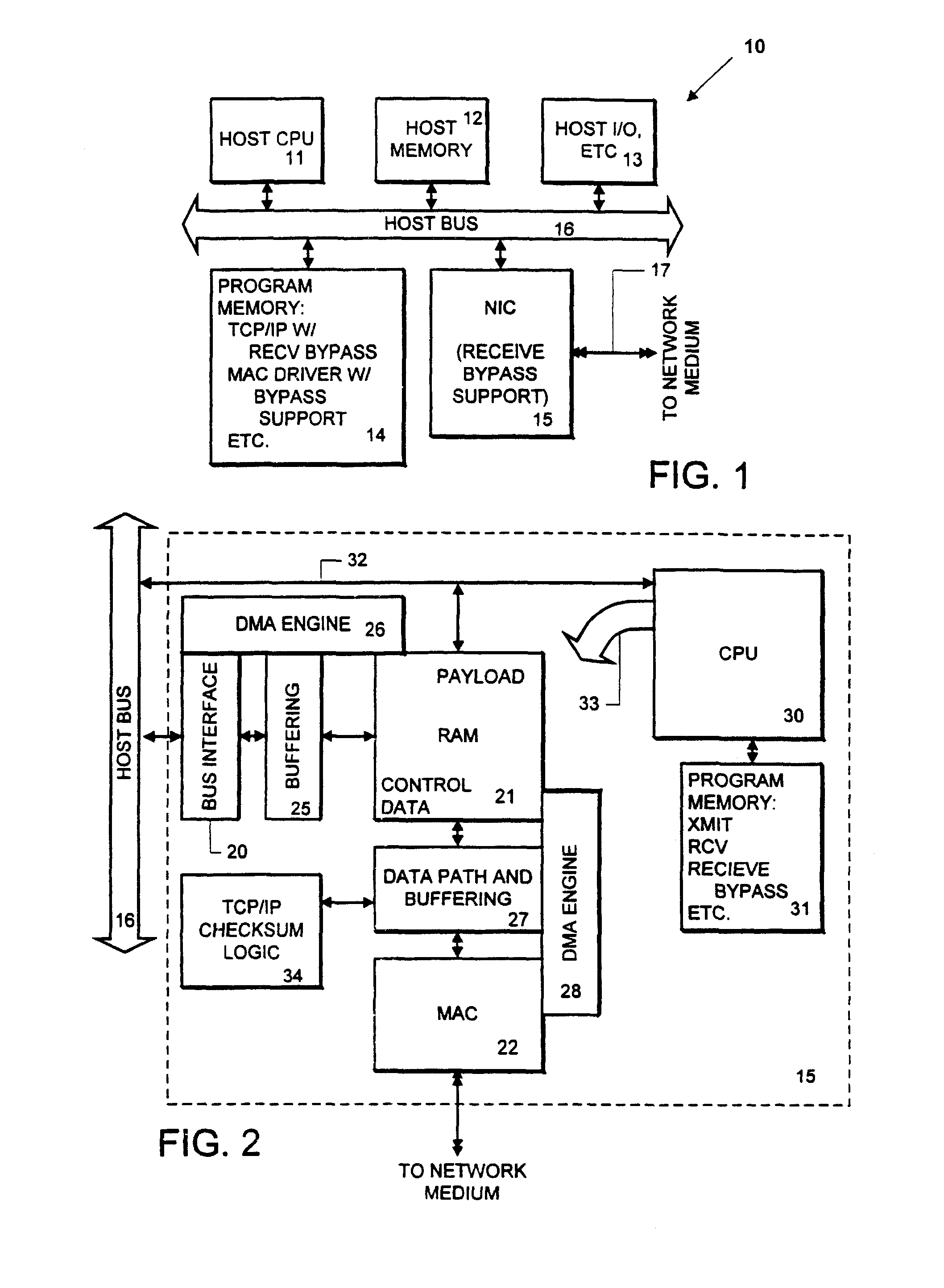
[0021]A detailed description of the present invention is provided with respect to FIGS. 1-5, in which FIGS. 1 and 2 illustrate a hardware system environment.

[0022]FIG. 1 shows a data processing system 10 which includes a host central processing unit 11, host memory 12, host input / output 13, such as keyboards, displays, printers, a pointing device and the like. The system also includes program memory 14 (usually part of the host memory block) and a network interface card 15. All of these elements are interconnected by a host system bus 16. The network interface card 15 provides for connection to a network medium as indicated at line 17.

[0023]FIG. 1 is a simplified diagram of a computer such as a personal computer or workstation. The actual architecture of such system is quite varied. This system for one example corresponds to a personal computer based on the Intel microprocessor running a Microsoft Windows operating system. Other combinations of processor and operating system are als...


PUM


Abstract

An adapter is provided with intelligence that allows it to separate the header parts of a packet being received from the payload it carries, and in most cases move the payload directly into a destination buffer at the application layer or file system layer. Copies by the intermediate layers of the protocol stack are bypassed, reducing the number of times that the payload of a communication must be copied by the host system. At the network interface, a plurality of packets is received, and the payload of each is bypassed directly into the target destination buffer. The network interface device identifies the packets which are in the sequence of packets carrying payload to be stored in the target buffer by the flow specification carried with such packets. Also, the packets carrying data payload for the file include a sequence number or other identifier by which the network interface is able to determine the offset within the target buffer to which the packet is to be stored.

Description

CROSS-REFERENCE TO RELATED APPLICATION[0001]This application is a reissue of U.S. patent application Ser. No 09 / 071,692 filed May 1, 1998, entitled “Receive Processing with Network Protocol Bypass” and issued as U.S. Pat. No. 6,246,683.BACKGROUND OF THE INVENTION[0002]1. Field of the Invention[0003]The present invention relates to processing of data in communication networks, and more particularly to the process of receiving a plurality of packets of data which relate to a common block of data, and efficiently providing such data to an application.[0004]2. Description of Related Art[0005]Network communications are often described with respect to layers of network protocols. According to a standard description, the layers include the physical layer, the datalink layer, the network layer (also called routing layer), the transport layer, and the application layer. Thus modem communication standards, such as the Transport Control Protocol TCP, the Internet Protocol IP, and IEEE 802 stan...

Claims


Application Information

Patent Timeline
Patent Type & Authority Patents(United States)
IPC IPC(8): H04L12/28H04L12/56
CPCH04L49/901H04L49/90H04L49/9042H04L69/16H04L69/161
Inventor CONNERY, GLENN WILLIAMREID, RICHARD
Owner HEWLETT-PACKARD ENTERPRISE DEV LP
Learn More