Narrow-band filter array with multi-cavity structure

A narrow-band filter and cavity structure technology, applied in the field of optical filters, can solve the problems of insufficient band-pass rectangularity, difficult engineering and practical requirements, and insufficient signal utilization, and achieve good band-pass rectangularity. , to meet the needs of engineering and practical use, the effect of simplifying the structure

Inactive Publication Date: 2007-08-29
SHANGHAI INST OF TECHNICAL PHYSICS - CHINESE ACAD OF SCI
View PDF5 Cites 0 Cited by
  • Summary
  • Abstract
  • Description
  • Claims
  • Application Information

AI Technical Summary

Problems solved by technology

However, the integrated optical filter arrays prepared by these methods are all single-cavity structures. Although they have the basic functions of integrated optical filter arrays and can achieve the purpose of light splitting, their band-pass rectangularity (or waveform) is still not enough. Well, in this way, the utilization rate of the signal in the band-pass range is not high enough, and it is difficult to really meet the engineering and practical requirements

Method used


Image

  • Narrow-band filter array with multi-cavity structure
  • Narrow-band filter array with multi-cavity structure

Examples


Embodiment Construction

[0020] The specific embodiment of the present invention is described in detail below in conjunction with accompanying drawing:

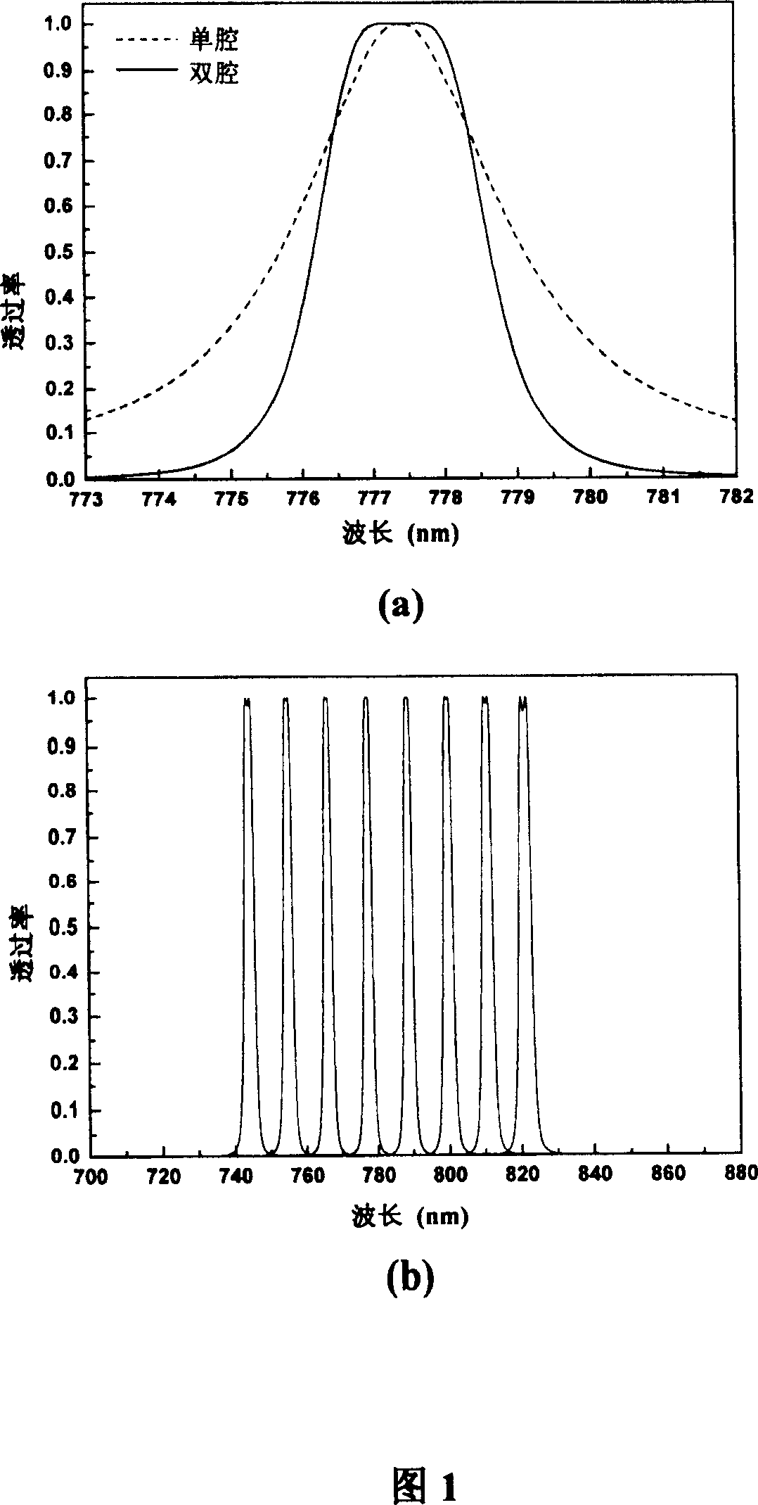
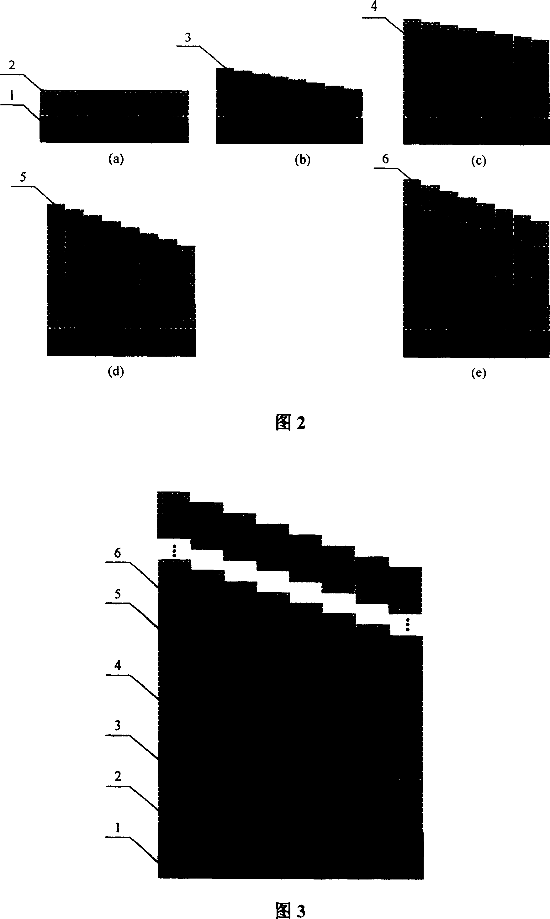
[0021] Taking the integrated 8-channel dual-cavity narrow-band filter array as an example, the film structure is H(LH) a-1 xL(HL) a H(LH) a yL(HL) a-1 H, design wavelength λ 0 777.4nm, L is a silicon dioxide film, H is a tantalum pentoxide film, a=6, the value of x=y is 1.7~2.4, and the point interval is 0.1. The specific preparation steps are as follows:

[0022] First, silicon dioxide film layers and tantalum pentoxide film layers H (LH) are alternately plated on the substrate 1 5 , constituting the lower film system 2, as shown in FIG. 2(a).

[0023] Then, the mask plate with windows in different regions is used to superimpose the coating film, the film system is xL, the value of x is 1.7-2.4, and the point interval is 0.1 to form the lower resonant cavity layer array 3 with different thicknesses. The number of units of the resonator film la...


PUM


Abstract

This invention discloses one thin band filter array with multiple chambers structures, which uses multiple F-P structure film system to form multiple chamber and forms resonance chamber array through composite coating film or etching method to achieve band pass peak of each micro thin band filter to realize the integration of different band pass filter slices. This structure is suitable for each wave section multi-chamber filter array.

Description

technical field [0001] The invention relates to an optical filter, in particular to a narrow-band filter array with a multi-cavity structure. Background technique [0002] Spectroscopic technology is one of the core technologies in multispectral detection technology. It has been widely used in environmental monitoring, biomedicine, science and technology agriculture, industrial process monitoring, as well as in ground or aviation and aerospace fields for missiles, meteors, clouds, rain, landforms, etc. Military and civilian fields such as the detection of targets and their backgrounds. Traditional spectroscopic methods mainly include gratings, prisms, filter wheels, and Fourier transform methods. Although most of these methods can perform full-spectrum scanning and high resolution, their disadvantages are that they all involve mechanical transmission devices, which not only limit the speed of information readout, but also greatly reduce the vibration resistance and reliabil...

Claims


Application Information

Patent Timeline
Patent Type & Authority Patents(China)
IPC IPC(8): G02B5/20G02B1/10
Inventor 王少伟陆卫陈效双李宁张波李志锋陈平平
Owner SHANGHAI INST OF TECHNICAL PHYSICS - CHINESE ACAD OF SCI
Why Eureka
Try Eureka