
Welding process and welding electric power unit

A welding method and technology of a power supply device, applied in welding equipment, arc welding equipment, manufacturing tools, etc., capable of solving problems such as defects in welding parts

Active Publication Date: 2007-09-26
SANSHA ELECTRIC MFG
View PDF4 Cites 0 Cited by
  • Summary
  • Abstract
  • Description
  • Claims
  • Application Information

AI Technical Summary

Problems solved by technology

This introduces welding slag into the crater of the workpiece, which leads to defects in the welded part

Method used


Image

  • Welding process and welding electric power unit
  • Welding process and welding electric power unit
  • Welding process and welding electric power unit

Examples


Embodiment Construction

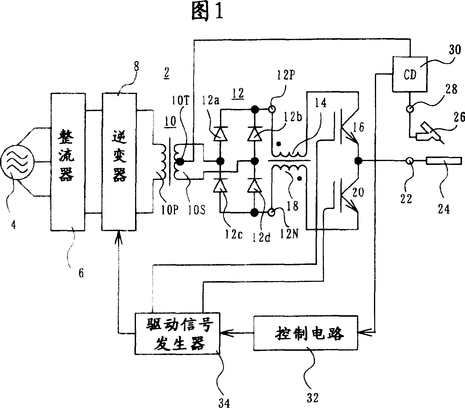
[0019] FIG. 1 shows a welding power supply device according to an embodiment of the present invention, which can be used for tungsten inert gas (arc) welding (TIG), and includes a DC power supply 2 .

[0020] The DC power supply 2 includes a rectification circuit 6 for rectifying the AC voltage output from, for example, the commercial AC power supply 4 . The rectified output of the rectification circuit 6 is supplied to a DC-to-high frequency conversion device, such as an inverter 8, through which it is converted into a high frequency voltage.

[0021] The high-frequency voltage is then supplied to the primary coil 10P of the transformer 10 . The secondary winding 10S of the transformer 10 has a center tap 10T. The high-frequency voltage induced in the secondary coil is rectified in a rectification circuit 12 . The rectification circuit 12 includes diodes 12a, 12b, 12c and 12d. The anode of the diode 12a is connected to one terminal of the secondary coil 10S, and the anode ...


PUM


Abstract

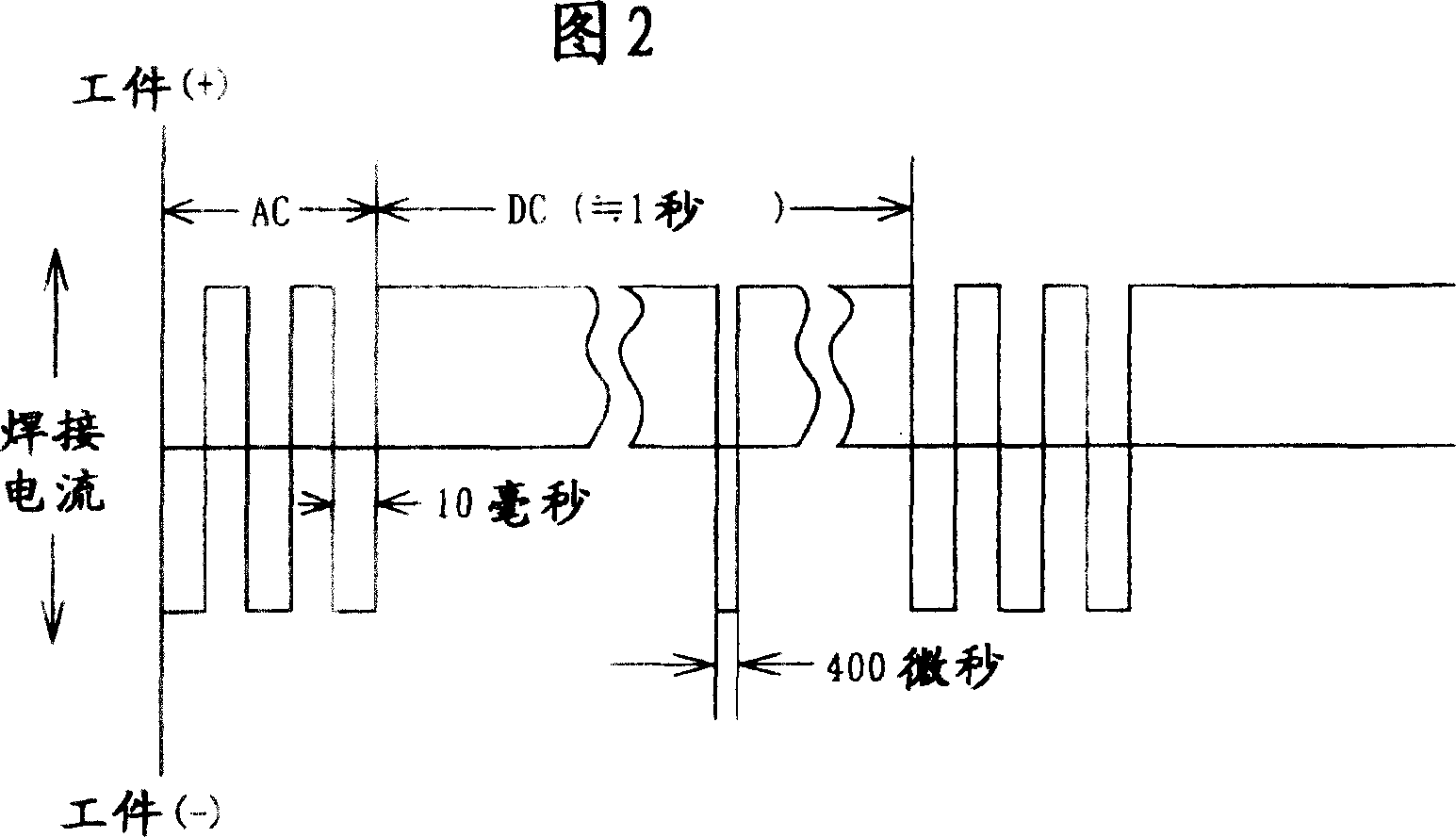
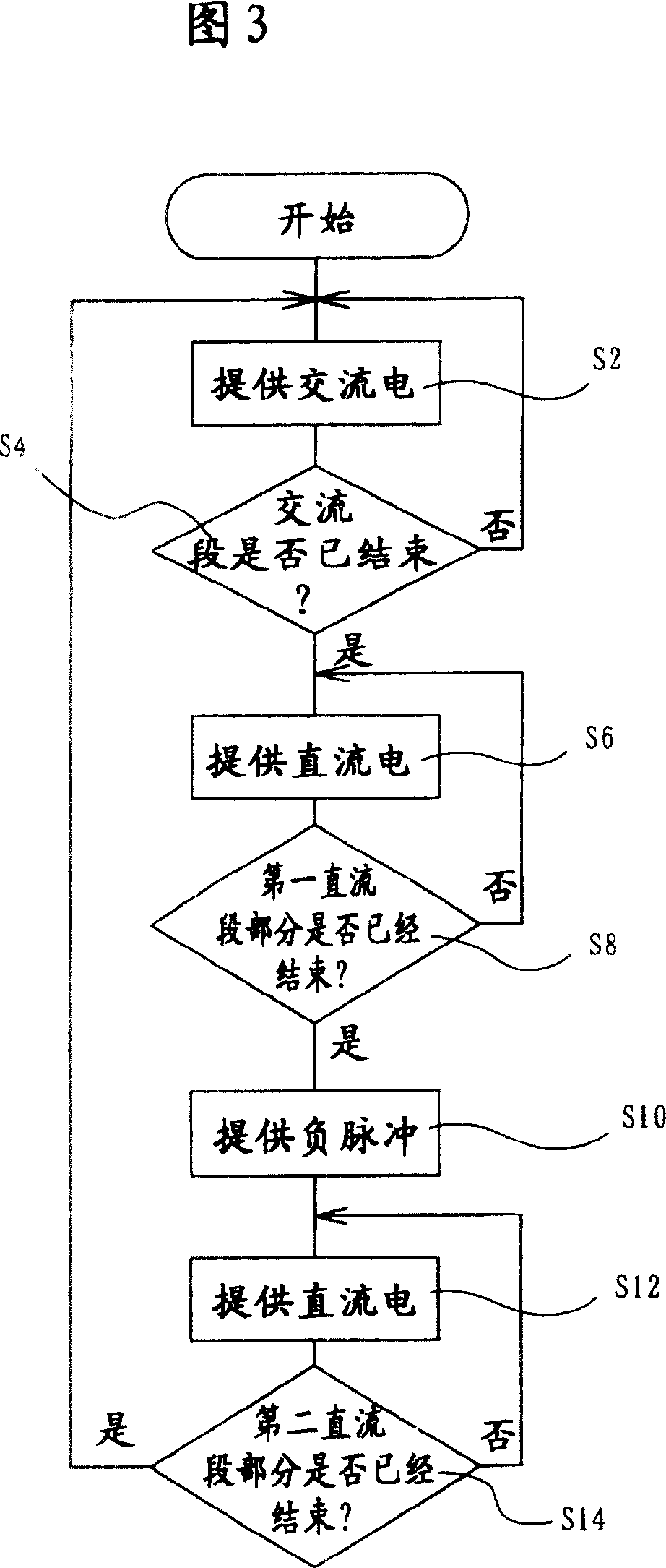
In the welder, IGBT(16) interrupts the current from the positive pole of the DC power source to the workpiece intermittently, IGBT(20) interrupts the current from the negative pole of the DC power source to the workpiece intermittently, and one control circuit and one drive signal generator circuit complete the switching control of IGBT(16) and IGBT(20) to generate one current circulation. The current circulation includes one AC section, in which IGBT(16) and IGBT(20) are made in on state alternately, and one followed DC section, in which IGBT(16) maintains in on state. Further, in the DC section, the control circuit and the drive signal generator circuit make IGBT(16) and IGBT(20) separately in off and on state simultaneously for at least one time before making IGBT(16) and IGBT(20) in on and off state separately.

Description

technical field [0001] The present invention relates to a method of welding workpieces of materials such as aluminum and magnesium, in which it is necessary to remove an oxide layer covering the surfaces of the workpieces, and to a welding power supply unit for carrying out the welding method. Background technique [0002] Japanese Patents 2,543,269 and 2,543,270, both registered on July 25, 1996, disclose techniques that can be used for welding the above workpieces. According to these Japanese patents, a power source is connected to a welding electrode and a workpiece to supply electric current thereto. A current cycle consists of an AC segment providing AC power, followed by a DC segment following the AC segment, and the cycle is repeated. In the DC section, a direct current flows from the workpiece to the electrode. According to patent 2,543,269, the proportion of the AC section in a cycle, ie the sum of the AC section and the DC section, is 30% to 80%. [0003] Accord...

Claims


Application Information

Patent Timeline
Patent Type & Authority Patents(China)
IPC IPC(8): B23K9/09B23K9/073B23K9/10B23K9/23H02M9/00
Inventor 森本猛石井秀雄
Owner SANSHA ELECTRIC MFG
Learn More