Motorised valve
A technology of electric valves and valve bodies, which is applied in the direction of lifting valves, valve devices, valve details, etc., can solve problems such as not particularly difficult, difficult, and not easy, and achieve the effects of easy manufacturing, simplified structure, and easy installation
- Summary
- Abstract
- Description
- Claims
- Application Information
AI Technical Summary
Problems solved by technology
Method used
Image
Examples
Embodiment 1
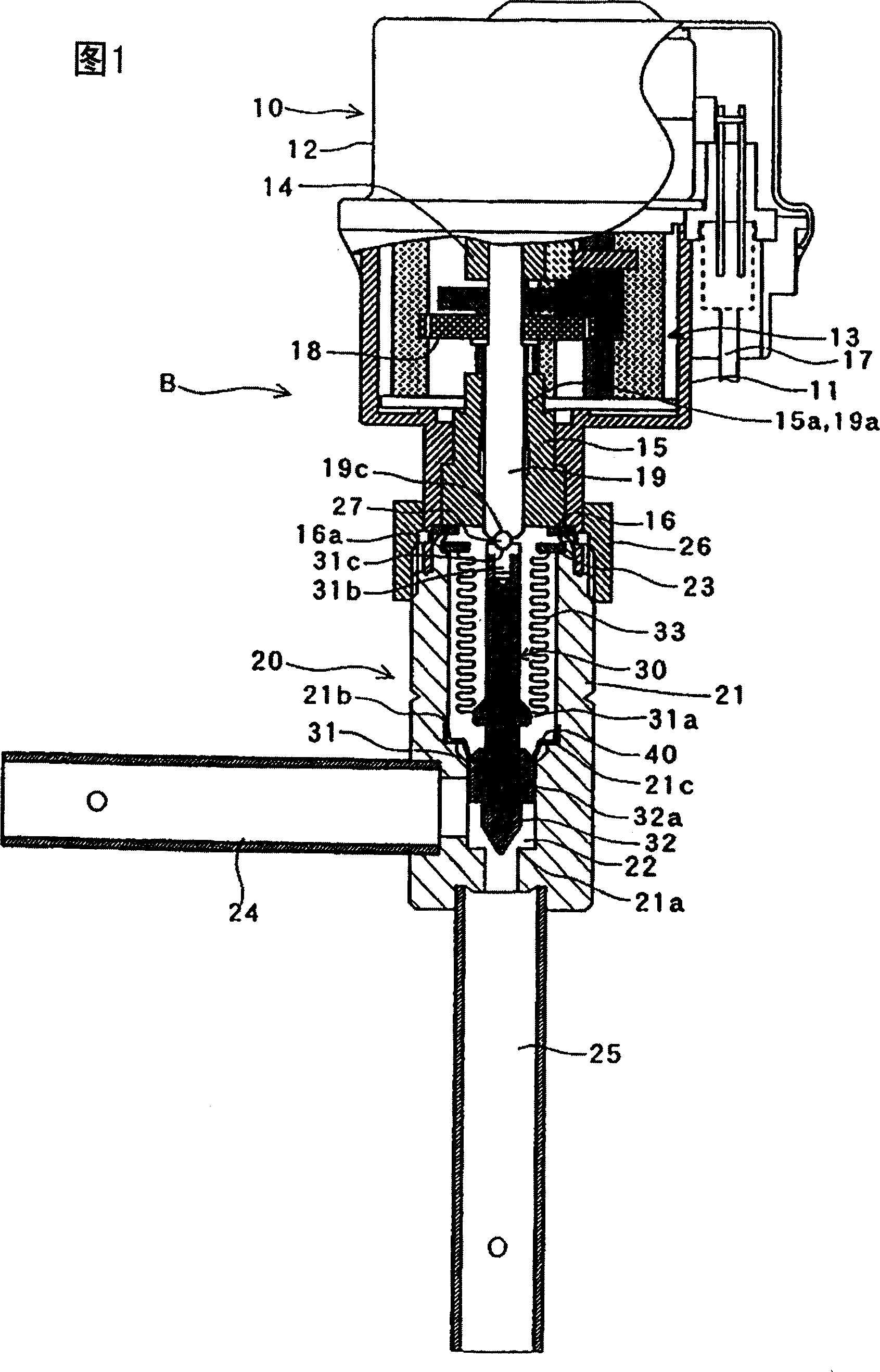
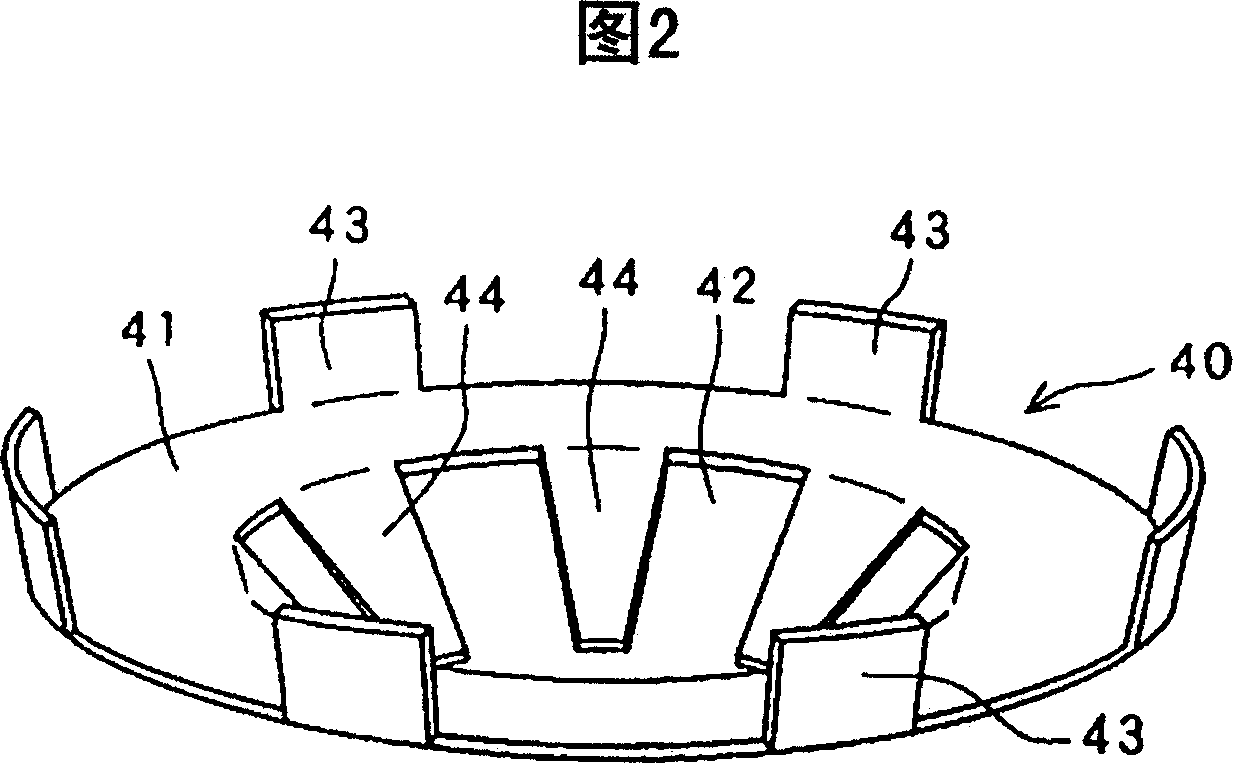
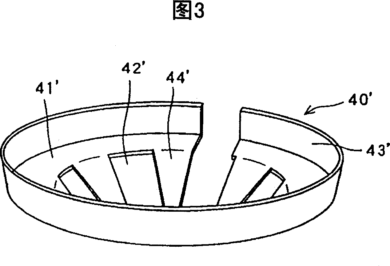
[0034] Embodiment 1 of the electric valve of the present invention will be described below with reference to the accompanying drawings. Fig. 1 is a schematic partial longitudinal sectional view thereof. Fig. 2 is a perspective view of its main part (stopper). Fig. 3 is a perspective view of another form of its main part (stopper). Fig. 4 is an explanatory diagram of the function of the main part (stopper).
[0035] The electric valve B is composed of a drive unit 10 and a valve body unit 20 .
[0036] First, the drive unit 10 will be described. The drive unit 10 is constituted by a stepping motor (no symbol) mounted on a case body 11 , a motor case 12 covering the stepping motor, and the like. The stepper motor is provided with leads 17 . A reduction mechanism 13 composed of various gears is disposed on the lower portion of the housing body 11 .
[0037] The reduction mechanism 13 is driven by a stepping motor, and is transmitted to an output rotary shaft 19 through an o...
Embodiment 2
[0055] Next, Embodiment 2 of the present invention will be described. Fig. 5 is a longitudinal sectional view of its main part, and the same constituent parts as those of the first embodiment are given the same reference numerals in Fig. 5 as those in Figs.
[0056] In Embodiment 2, when the valve body 30 moves upward and protrudes above the valve body 21, the contact portion 32b of the valve 32 that is in contact with the stopper 40 is not provided with the engaging step 32a as in Embodiment 1, but is in contact with the stopper 40. A sloped flat face with the same other faces. According to the structure of the second embodiment, the structure of the valve 32 is simple and can be processed easily. In addition, in Embodiment 2, the lower edge of the portion 44 of the stopper 40 that contacts the valve body (the contact surface to the contact portion 32b of the valve 32) may be an inclined surface that matches the inclination angle of the contact portion 32b.
[0057] Moreove...
Embodiment 3
[0059] Next, Embodiment 3 of the present invention will be described, and FIG. 6 is a longitudinal sectional view of its main parts. Fig. 7 is a further enlarged cross-sectional view of the main part of Fig. 6 . FIG. 8 is an enlarged sectional view of the stopper 50 . In the third embodiment, the same components as those in the above-mentioned first embodiment are assigned the same symbols in FIGS. 6 to 7 as those in FIGS. 1 to 4 , and therefore descriptions thereof are omitted.
[0060] On a portion of the inner surface of the valve body 21, an attachment recess C for a stopper 50 to be described later is formed. The mounting recess C is composed of an upper fitting step 21b, a back support portion 21d and a lower fitting step 21e below the back support portion 21d. The back support portion 21d is continuous with the upper fitting step 21b, and has a uniform inner diameter substantially parallel to the inner surface portion of the valve body 21 below it. Preferably, the di...
PUM
 Abstract
Description
Claims
Application Information
 - R&D
- Intellectual Property
- Life Sciences
- Materials
- Tech Scout
- Unparalleled Data Quality
- Higher Quality Content
- 60% Fewer Hallucinations
Browse by: Latest US Patents, China's latest patents, Technical Efficacy Thesaurus, Application Domain, Technology Topic, Popular Technical Reports.
© 2025 PatSnap. All rights reserved.Legal|Privacy policy|Modern Slavery Act Transparency Statement|Sitemap|About US| Contact US: help@patsnap.com


