Shallow trench isolation structure making method

A technology of isolation structure and manufacturing method, which is applied in semiconductor/solid-state device manufacturing, electrical components, circuits, etc., can solve problems such as component leakage current, liner 212 damage, shallow trench isolation structure 216 poor isolation function, etc., to achieve The effect of uniform thickness and avoiding leakage current

Inactive Publication Date: 2007-09-26
POWERCHIP SEMICON CORP
View PDF4 Cites 0 Cited by
  • Summary
  • Abstract
  • Description
  • Claims
  • Application Information

AI Technical Summary

Problems solved by technology

Therefore, when the silicon oxide layer is formed by high-density plasma chemical vapor deposition in subsequent steps, the liner 212 of the corner 214 is too thin and is easily damaged by ion breakdown, thereby causing the isolation function of the shallow trench isolation structure 216 to fail. Good, and easy to cause the problem of component leakage current

Method used


Image

  • Shallow trench isolation structure making method
  • Shallow trench isolation structure making method
  • Shallow trench isolation structure making method

Examples


Embodiment Construction

[0040] Next, the embodiments of the present invention will be described in detail, and the embodiments will be explained with the accompanying drawings. The depiction is in simplified form and not exact dimensions.

[0041] 3A to 3G are cross-sectional views of a manufacturing process of a preferred shallow trench isolation structure of the present invention.

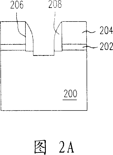
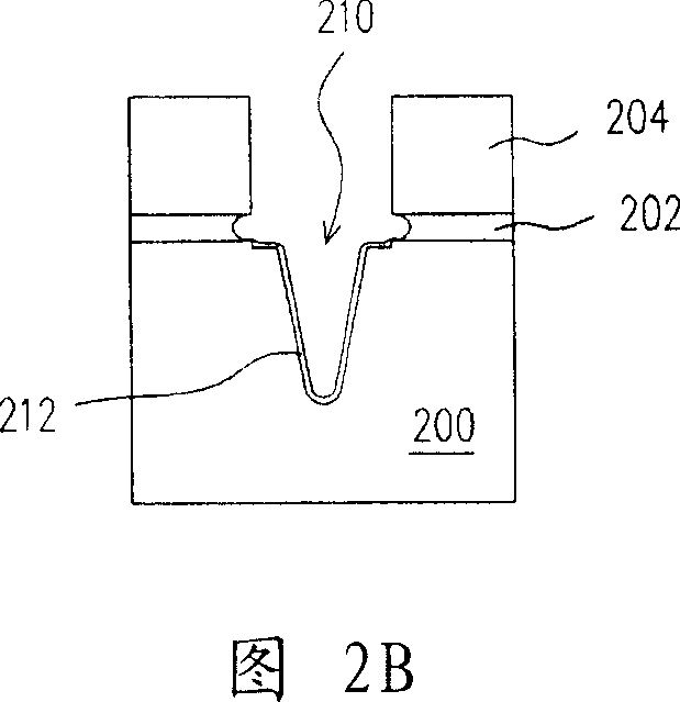
[0042] Referring to FIG. 3A , the present invention provides a method for manufacturing a shallow trench isolation structure. Firstly, a substrate 300 is provided, and a pad layer 302 is formed on the substrate 300. The material of the pad layer 302 includes silicon dioxide, and the formation method is, for example, a thermal oxidation method. Of course, the material of the liner layer 302 may also be any other suitable material. Then, a silicon liner layer 304 is laid on the liner layer 302 . The material of the silicon liner layer 304 includes polysilicon, amorphous silicon, or single crystal silicon, and its forma...


PUM


Abstract

This invention relates to one shallow groove isolation structure process method, which comprises the following steps: providing one baseboard with orderly formed underlay layer, silicon pad and one mask layer; Then make pattern on mask layer and silicon pad layer to form one open exposed out; Then forming one gap on open side and removing part underlay layer to expose the base and Using mask layer with gap as etch mask to remove part base to form one groove on the base; Then removing gap wall and processing the repeated etch to contract underlay pad; Then filling one isolation layer into groove and removing the pattern mask layer to form the shallow isolation structure.

Description

technical field [0001] The invention relates to a method for manufacturing a semiconductor element, in particular to a method for manufacturing a shallow trench isolation (shallow trench isolation, STI) structure. Background technique [0002] Today, with the vigorous development of integrated circuits, the miniaturization and integration of components is an inevitable trend, and it is also an important topic for active development in all walks of life. When the size of the components is gradually reduced and the integration level is gradually increased, the isolation structure between the components must also be reduced, so the difficulty of the component isolation technology is also gradually increased. Component isolation has a field oxide layer (field oxide) formed by local oxidation (LOCOS). Since the field oxide layer is limited by the formation of the bird's beak (bird's beak) region of its shape, it is easy to cause leakage current ( leakage current), so that the im...

Claims


Application Information

Patent Timeline
Patent Type & Authority Patents(China)
IPC IPC(8): H01L21/76
Inventor 曾祥铭赖佳平陈志铭毕嘉慧
Owner POWERCHIP SEMICON CORP
Why Eureka
Try Eureka